Numerical control machining system for die

A processing system and mold technology, applied in metal processing equipment, metal processing machinery parts, manufacturing tools, etc., can solve the problems of large size error, poor surface continuity, and lack of precision of the mold surface, so as to reduce wear and avoid movement Unsmooth, increased precision effect

Active Publication Date: 2021-08-24
威海恒科精工有限公司
View PDF7 Cites 0 Cited by
  • Summary
  • Abstract
  • Description
  • Claims
  • Application Information

AI Technical Summary

Problems solved by technology

[0004] In order to make up for the deficiencies of the existing technology, this type of processing equipment cannot realize the processing of high-precision molds and mold handicrafts, and most of the molds produced have large errors in mold surface dimensions, poor surface continuity, and large fluctuations. With the problem of too high precision, the present invention proposes a mold numerical control machining system

Method used


Image

  • Numerical control machining system for die
  • Numerical control machining system for die
  • Numerical control machining system for die

Examples


Embodiment approach

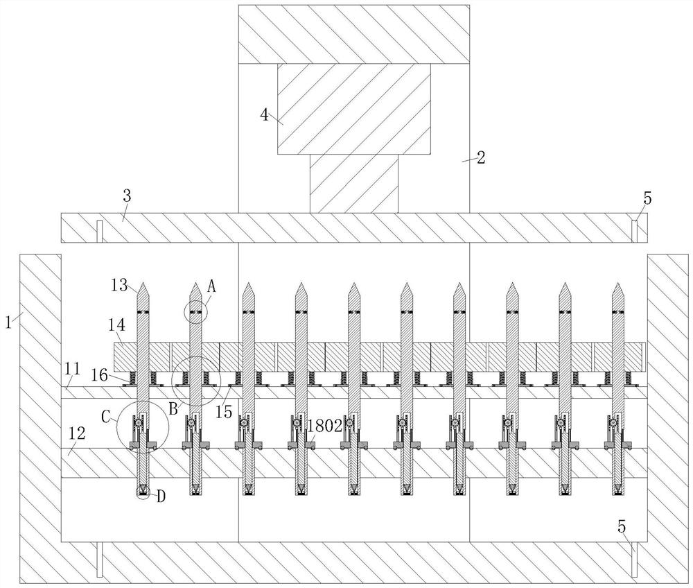
[0038] As an embodiment of the present invention, the upper surface of the second fixing plate 12 is provided with a second chute 35 on the peripheral side of each rotating rod 13; the cross section of the second chute 35 is hemispherical; The lower surface of each ring 1802 is provided with a third chute 36; a plurality of steel balls 6 evenly arranged are slidably connected in the third chute 36; the second chute 35 corresponds to the third chute 36 set up.

[0039] During work, when the blade 32 cuts the mould, the ring 1802 rotates with the rotating rod 13, and the steel ball 6 slides in the second chute 35, so as to prevent the lower end of the ring 1802 from directly contacting the second fixed plate 12. The fixed plate 12 and the ring 1802 are worn out, and the ring 1802 and the blade 32 rotate with the rotating rod 13 at the same time. A plurality of steel balls 6 make the ring 1802 rotate more smoothly, so that the blade 32 can cut more smoothly. The material of the ...

specific Embodiment approach

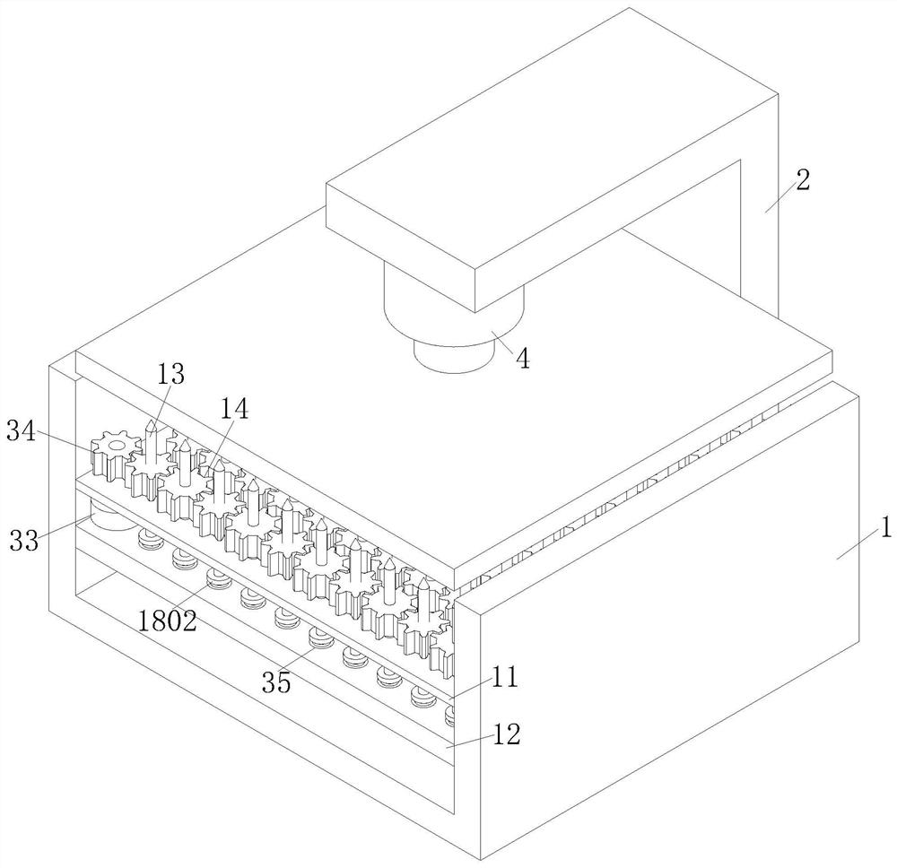
[0048] When working, the material of the mold to be manufactured is fixed in the bolt hole 5 on the shell 1 by bolts, and the sample of the mold is fixed in the bolt hole 5 on the lower surface of the die-casting plate 3 by bolts, and the drive is controlled by the controller after fixing The cylinder 4 and the motor 33 work to drive the extended end of the cylinder 4 to control the downward movement of the die-casting plate 3, so that the sample piece squeezes the tip of the rotating rod 13. At this time, the first driven gear 14 moves downward with the rotating rod 13, The first driven gear 14 squeezes the first spring 16 so that the first spring 16 is compressed, and because the first driven gear 14 is meshed with the driving gear 34, the first driven gear 14 keeps rotating, so that the rotating rod 13 is in the second position. The bottom of the first bearing 15 rotates, the rotating rod 13 above the first bearing 15 does not rotate, and the first driven gear 14 twists the ...


PUM


Abstract

The invention belongs to the technical field of die machining, and particularly relates to a numerical control machining system for a die. The numerical control machining system comprises a shell, a support, a die-casting plate and a controller; the support is in an L shape, one end of the support is fixedly connected to the side wall of the shell, the other end of the support extends to the position above the shell, a driving air cylinder is fixedly connected between the other end of the support and the upper surface of the die-casting plate, and the shell is designed in a concave shape; a first fixing plate and a second fixing plate are fixedly connected to the inner side wall of the shell; the first fixing plate is located above the second fixing plate; rotating rods are uniformly arranged on the surface of the first fixing plate; the rotating rods penetrate through the first fixing plate and the second fixing plate, and the lower ends of the rotating rods extend out of the lower surface of the second fixing plate; first driven gears are fixedly connected to the positions, at the upper end part of the first fixing plate, of the peripheral sides of the rotating rods; and the upper end of the first fixing plate is rotationally connected with a driving gear. According to the numerical control machining system, the die-casting plate can be controlled according to sample plates with different shapes, so that the sample plates are in contact with and extrude the tip parts of the rotating rods below, and preliminary cutting and forming of different dies are realized.

Description

technical field [0001] The invention belongs to the technical field of die processing, in particular to a die numerical control processing system. Background technique [0002] In response to the current market demand, the demand for molds is increasing, and the quality requirements are also getting higher and higher. However, the manufacturing of molds is relatively difficult. Compared with general mechanical processing, there are many particularities. The manufacturing requirements of molds are relatively high. Not only requires good processing quality, but also high surface requirements, complex shapes, and high material hardness requirements. In many cases, single-piece production is required. For this situation, the combination of numerical control technology and mold manufacturing will promote the precision and efficiency of molds. The characteristics of processing are: high processing efficiency, high processing precision, and can realize networked and intelligent pro...

Claims


Application Information

Patent Timeline
Patent Type & Authority Applications(China)
IPC IPC(8): B23Q5/34B23Q3/00B23Q11/00B23D79/00
CPCB23Q5/34B23Q3/00B23Q11/0042B23D79/00
Inventor 陈鸿孔永峰赵文
Owner 威海恒科精工有限公司
Why Eureka
Try Eureka