
Mold and injection molding method using the mold

A technology for molds and male mold cores, which is applied in the field of molds and injection molding, and can solve problems such as increasing mold costs, damaging molds, and easily twisting male mold cores when teeth are inserted

Inactive Publication Date: 2009-07-01
三营超精密光电(晋城)有限公司
View PDF0 Cites 0 Cited by
  • Summary
  • Abstract
  • Description
  • Claims
  • Application Information

AI Technical Summary

Problems solved by technology

Therefore, it is easy to twist the core of the male die when the teeth are inserted, thereby damaging the mold, thereby increasing the cost of repairing or replacing the mold
Moreover, while the tooth is twisting the male core, it may cause damage to the tooth itself.

Method used


Image

  • Mold and injection molding method using the mold

Examples


Embodiment Construction

[0010] The present invention will be further described in detail below in conjunction with the accompanying drawings.

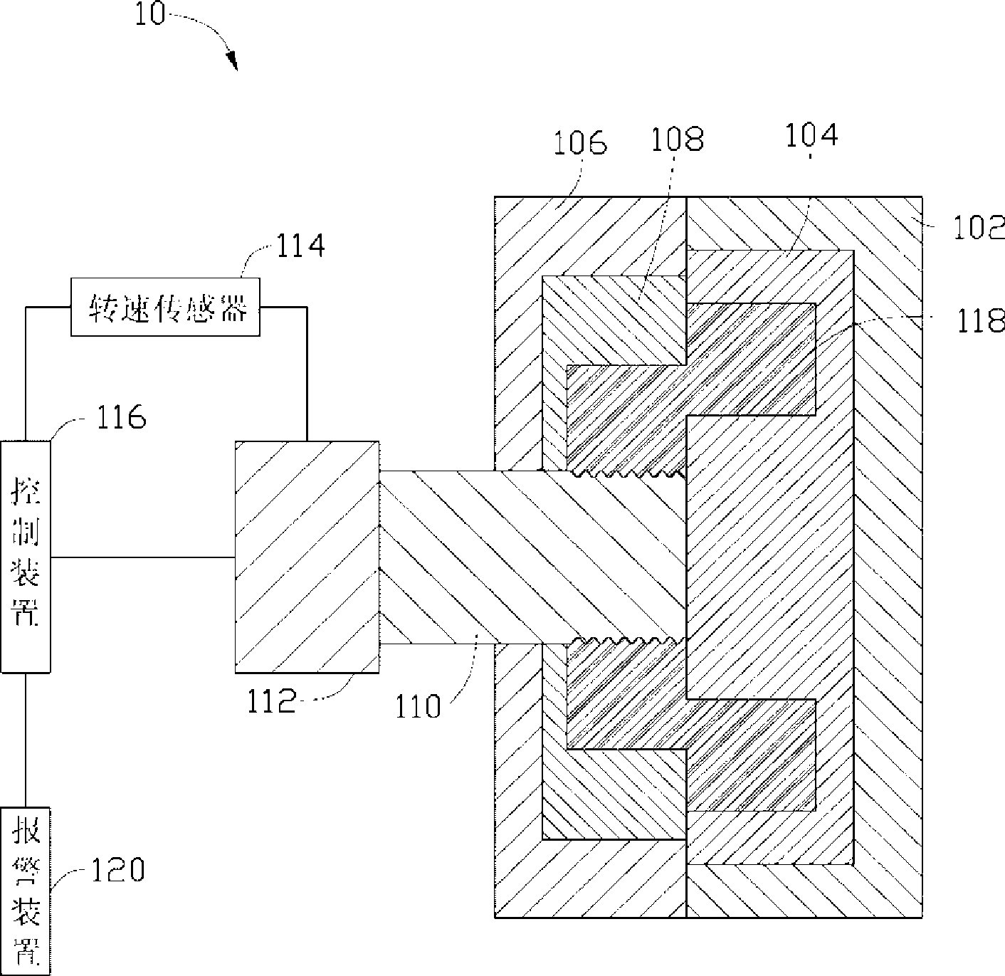
[0011] see figure 1 , The mold 10 of the preferred embodiment of the present invention includes a female template 102, a female mold core 104, a male template 106, a male mold core 108, a tooth insert 110, a motor 112, a speed sensor 114, a control device 116 and an alarm device 120.

[0012] The female template 102 and the male template 106 are arranged oppositely, the female template core 104 is set in the female template 102 , and the male mold core 108 is set in the male template 106 . The female mold core 104 is set opposite to the male mold core 108, and the female mold core 104 cooperates with the male mold core 108 to form a mold cavity (not shown), and the mold cavity is used for injection molding workpieces. In this embodiment, the workpiece to be injection molded is the mirror holder 118 .

[0013] The dental implant 110 is pierced in the male te...


PUM


Abstract

The invention relates to a mould. The mould comprises a male mould plate, a male mould core, a female mould plate, a female mould core, a tooth, a motor, a rotational speed sensor and a control device, wherein the male mould core is arranged inside the male mould plate; the female mould core is arranged inside the female mould plate; the male mould core and the female mould core are matched to form a mould cavity; the tooth is inserted into the male mould plate and the female mould plate; the tooth is provided with a first end and a second end which are relative; the first end has a screw thread structure; the motor is connected with the second end of the tooth; the motor is used for driving the tooth to enter or recede the mould cavity; the rotational speed sensor is connected with the motor and is used for sensing the rotational speed of the motor; the rotational speed sensor is in electric connection with the control device and inputs the sensed rotational speed to the control device; the control device and the motor are in electric connection to control the rotation of the motor; the control device has a preset rotational speed range; and when the rotational speed sensed by the rotational speed sensor is beyond the preset rotational speed range, the control device controls the motor to stop rotation.

Description

technical field [0001] The invention relates to a mold and an injection molding method, in particular to a mold with teeth and an injection molding method using the mold. Background technique [0002] With the development of optical imaging technology, lens modules are widely used in various imaging devices such as digital cameras and video cameras (see Capturing images with digital still cameras, Micro, IEEE Volume: 18, issue: 6, Nov.-Dec.1998 Page(s): 14-19). Electronic devices such as mobile phones and notebooks integrated with lens modules are favored by many consumers. [0003] The lens module generally includes a lens base and a lens barrel, etc. The lens base has an internal thread structure, and the lens barrel has an external thread structure, and the lens base and the lens barrel are matched through threads. The mirror base is usually manufactured by injection molding, and the internal thread structure of the mirror base is generally molded by teeth. Before inje...

Claims


Application Information

Patent Timeline
IPC IPC(8): B29C45/80B29C45/33B29C45/17B29L1/00
Inventor 林后尧
Owner 三营超精密光电(晋城)有限公司
Learn More