Automatic casting machine

An automatic pouring and ladle technology, which is applied in the control of pouring molten metal from the ladle, metal processing equipment, casting equipment, etc., can solve the problems of increased production cost, potential safety hazards, personal injury, etc., and achieves low structural cost. , and the effect of removing potential safety hazards and isolating heat transfer

Active Publication Date: 2016-07-06
西安合力汽车配件有限公司
View PDF5 Cites 2 Cited by
  • Summary
  • Abstract
  • Description
  • Claims
  • Application Information

AI Technical Summary

Problems solved by technology

[0002] Automatic pouring machines are widely used in existing processing systems. In order to improve production efficiency, the current pouring machines are all large-scale pouring machines, which can cast multiple molds at one time; the structure of a single-processing pouring machine stays at The traditional manual operation or a single processing function is completed by a large pouring machine; the safety hazard of manual operation is very large, and the high temperature molten iron is very easy to cause huge personal injuries through high temperature transfer and molten iron splashing during the pouring process; the single single processing function of a large pouring machine The operation of the secondary processing is complicated, and the overkill is underutilized, which increases the production cost

Method used


Image

  • Automatic casting machine
  • Automatic casting machine
  • Automatic casting machine

Examples


specific Embodiment approach

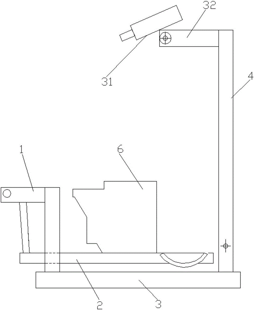
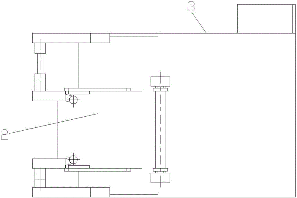
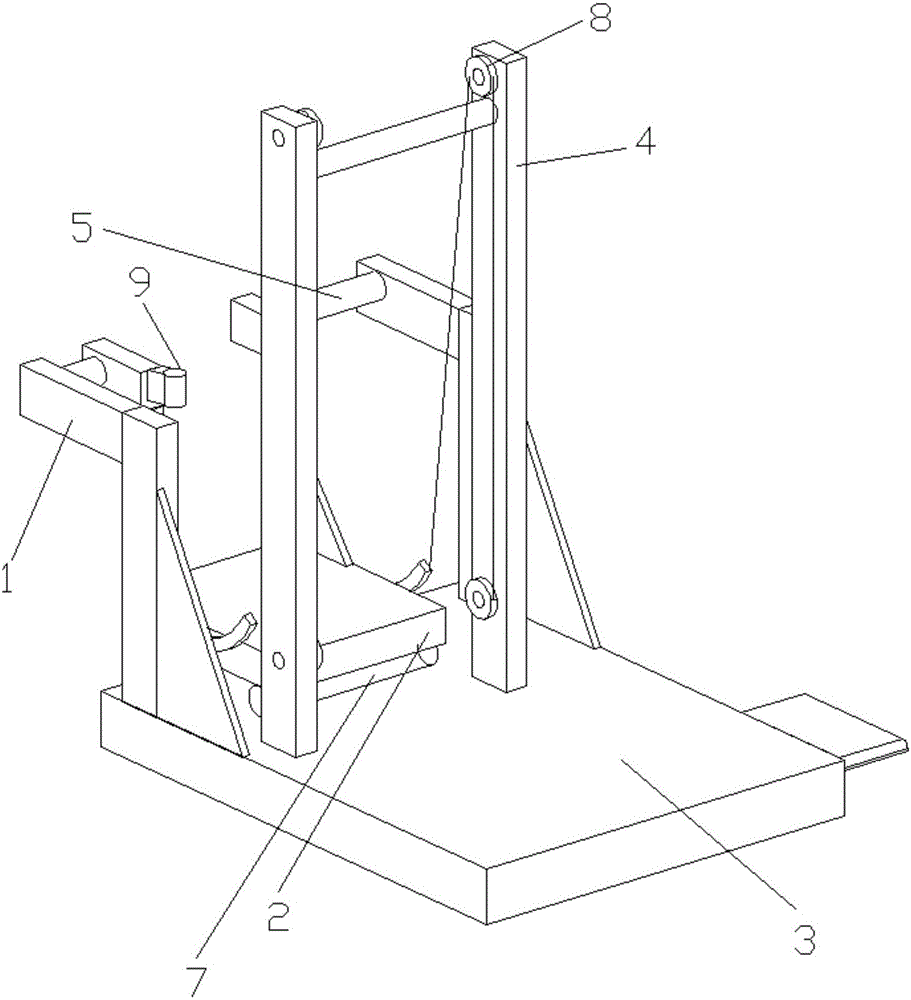
[0043] Such as Figure 1-17As shown, it shows a specific embodiment of the present invention. As shown in the figure, the present invention discloses an automatic pouring machine, which includes an upper platform 3, and a bracket for rotating and installing a rotating bracket 2 is arranged in parallel on the upper platform. 1 and a frame 4 for installing the pulley; the frame is arranged at the rear of the support; the frame includes two columns arranged parallel to each other, and the pulley includes an upper pulley 8 and a lower pulley, and the upper pulley and the lower pulley are rotatably installed on On the surface of the opposite side of the two uprights; the end of the rotating bracket near the frame side is fixedly connected with a rope 27, and the far end of the rope is pulled by a motor after passing through the upper pulley and the lower pulley; the rotating bracket The end on the side away from the frame is rotatably mounted on the bracket;

[0044] As shown in t...


PUM


Abstract

The invention discloses an automatic casting machine, which comprises an upper platform, a support frame and a framework, wherein the support frame is arranged on the upper platform in a parallel way and is used for rotationally installing a rotating bracket; the framework is used for installing pulleys; the framework is arranged at the back side of the support frame; the framework comprises two upright posts in parallel arrangement in opposite directions; the pulleys comprise an upper pulley and a lower pulley; the upper pulley and the lower pulley are rotationally arranged on the surface of one opposite side to the two upright posts; the end part of one side, near the framework, of the rotating bracket is fixedly connected with a rope; the far end of the rope passes through the upper pulley and the lower pulley and is then pulled through being driven by a motor; the end part of one side, far away from the framework, of the rotating bracket is rotationally arranged on the support frame; a pouring ladle used for pouring out molten iron is arranged on the rotating bracket.

Description

technical field [0001] The invention relates to an automatic pouring machine, which can realize the process of pouring molten iron into a mold through a ladle. Background technique [0002] Automatic pouring machines are widely used in existing processing systems. In order to improve production efficiency, the current pouring machines are all large-scale pouring machines, which can cast multiple molds at one time; the structure of a single-processing pouring machine stays at The traditional manual operation or a single processing function is completed by a large pouring machine; the safety hazard of manual operation is very large, and the high temperature molten iron is very easy to cause huge personal injuries through high temperature transfer and molten iron splashing during the pouring process; the single single processing function of a large pouring machine The operation of the secondary processing process is complicated, and the overkill is underutilized, which increase...

Claims


Application Information

Patent Timeline
Patent Type & Authority Applications(China)
IPC IPC(8): B22D37/00
CPCB22D37/00
Inventor 叶少腾张义涛
Owner 西安合力汽车配件有限公司
Why Eureka
Try Eureka