Radial adjusting mechanism of Y-shaped rolling mill

A technology for adjusting mechanism and rolling mill, applied in the direction of metal rolling mill stand, metal rolling stand, metal rolling, etc., can solve the problem of high manufacturing cost and maintenance cost, large and complex structure of C-shaped stand, and can not adapt to special-shaped products Rolling and other problems, to achieve the effect of online rapid automatic accurate adjustment, saving rolling line space, fast and accurate adjustment

Active Publication Date: 2016-07-06
沈阳重机重矿机械设备制造有限公司 +1
View PDF10 Cites 4 Cited by
  • Summary
  • Abstract
  • Description
  • Claims
  • Application Information

AI Technical Summary

Problems solved by technology

This type of rolling mill is a three-roll reducing and sizing rolling mill. It consists of three 120°-distributed rolls forming a triangular pass. The rolled piece is rolled and processed. When the rolled piece is deformed, it bears compressive stress in three directions. The Y-shaped rolling mill It has the function of online rapid radial adjustment, but the problem is that the characteristics of the three main shafts distributed at 120° in the Y-type rolling mill determine that the transmission of one main shaft is distributed to three directions through the gear set mechanism, so that the C-shaped frame structure In addition, the KOCKS rolling mill adopts the installation of eccentric sleeves on each main shaft, and the three eccentric sleeves are meshed with bevel gears. One of the eccentric sleeves is connected with the external bevel gear, and the external bevel gear drives the entire bevel gear set to rotate, so that The three eccentric sleeves rotate synchronously to adjust the pass between the rolls. Another problem with this structure is that the number of transmission gears is large and the precision of manufacturing and installation is high, and the manufacturing cost and maintenance cost are also very high. In addition, This structure makes the three rollers advance and retreat synchronously. Although the position of the rollers and the roll gap can be adjusted concentrically, this structure requires high precision in initial processing and assembly, and also requires very high manufacturing and assembly precision of the entire eccentric set and bevel gear set. , which brings great difficulty to processing and manufacturing and increases the cost of equipment. At the same time, this structure can only complete the rolling of fixed-shaped products, and cannot adapt to the rolling of special-shaped products.

Method used


Image

  • Radial adjusting mechanism of Y-shaped rolling mill
  • Radial adjusting mechanism of Y-shaped rolling mill
  • Radial adjusting mechanism of Y-shaped rolling mill

Examples


specific Embodiment approach 1

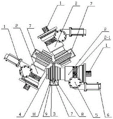
[0032] Such as figure 1 As shown, the technical solution adopted by the present invention includes three main shafts 1, and a main eccentric sleeve 2 and a secondary eccentric sleeve 4 are installed on each main shaft 1, wherein the main eccentric sleeve 2 is an eccentric sleeve with a worm gear, and the eccentric sleeve with a worm gear The structure of the main eccentric sleeve 2 is that an integrated worm wheel 2-1 is processed on the body of the main eccentric sleeve 2 to form a main eccentric sleeve 2 with a worm gear integrated with the body of the worm wheel 2-1 and the main eccentric sleeve 2, so that Improve the strength of the eccentric sleeve, eliminate the assembly gap between the worm gear and the eccentric sleeve, and avoid assembly accuracy errors; the main eccentric sleeve 2 with the worm wheel and the secondary eccentric sleeve 4 are connected through the eccentric sleeve connector 3, and each belt A worm gear mechanism 5 is installed on the main eccentric sle...

specific Embodiment approach 2

[0035] Such as figure 1 , image 3 , Figure 4 with Figure 5 As shown, it is the same as the primary transmission described in Embodiment 1, the difference is that a secondary worm gear 15 is installed on the first worm 13 in the primary transmission, the secondary worm gear 15 is connected to the second worm 16, and the secondary worm gear 15 Installed in the second support sleeve 14-2 through the bearing, the second support sleeve 14-2 is connected with the rack of the rolling mill, when the second worm 16 rotates, it drives the second worm wheel 15 to rotate, and the second worm wheel drives the first The worm 13 rotates, the first worm 13 drives the main eccentric sleeve 2 with worm gear to rotate, and drives the secondary eccentric sleeve 4 to rotate together through the eccentric sleeve connector 3, so that the main shaft 1 rises or falls, and the roll 7 is driven to rise or fall, and the roll diameter is completed. To the precise adjustment of the position, the serv...


PUM


Abstract

The invention discloses a radial adjusting mechanism of a Y-shaped rolling mill and aims to overcome the problems that some of the Y-shaped rolling mills have no radial adjusting devices, the rolling reduction is non-adjustable, or the radial adjustment is achieved under unreasonable transmission structures, the adjustment amount is extremely small and difficultly meets the basic requirement of steady transmission, the service life of the rolling mill is seriously influenced, or the structure is complex, the processing and manufacturing difficulty is high, the cost is high, and the rolling mill is unsuitable for rolling special-shaped products. The radial adjusting mechanism of the Y-shaped rolling mill is characterized in that a main eccentric sleeve and a secondary eccentric sleeve are mounted on each main shaft; a worm mechanism sleeves each main eccentric sleeve; the worm mechanism drives the eccentric sleeves to rotate and accurately adjust the radial position of the roller. The radial adjusting mechanism of the Y-shaped rolling mill has the beneficial effects that on-line adjustment can be implemented; the requirements of the manufacturing accuracy and the assembly accuracy are relatively low; the adjusted radial position accuracy is high; the worms are located on front and back surfaces or the sides of the rolling mill; the servo control motor is conveniently mounted; the radial position can be rapidly and accurately adjusted on line.

Description

technical field [0001] The invention belongs to the technical field of metal rolling, in particular to a radial adjustment mechanism of a Y-shaped rolling mill. Background technique [0002] There are three roll shafts installed on the frame of the Y-type rolling mill, which are perpendicular to the rolling center line and arranged at 120° to each other. High strength, high brittleness and other metal materials that are difficult to be rolled by ordinary rolling mills, and has the characteristics of high geometric precision of the rolled workpiece surface, and is widely used in special steel, titanium alloy, magnesium alloy, tungsten-molybdenum alloy and other special steels. In the production of materials with high rolling difficulty. Some of the Y-shaped rolling mills in the prior art adopt centralized transmission of bevel gear sets, or drive through C-shaped stand gearbox sets. Their common feature is that the rotation of one main shaft driven by one motor is distribute...

Claims


Application Information

Patent Timeline
Patent Type & Authority Applications(China)
IPC IPC(8): B21B31/26
CPCB21B31/26
Inventor 元钢马影刘玉凤元靖云苏金玲赵飞蔺任志
Owner 沈阳重机重矿机械设备制造有限公司
Why Eureka
Try Eureka