Inductor assembly and manufacturing method thereof
A manufacturing method and inductor technology, which is applied in the field of inductors, can solve the problems of electromagnetic interference and low space utilization of inductors, and achieve the effects of reducing volume, improving magnetic shielding effect, and good magnetic shielding effect
- Summary
- Abstract
- Description
- Claims
- Application Information
AI Technical Summary
Problems solved by technology
Method used
Image
Examples
no. 1 example
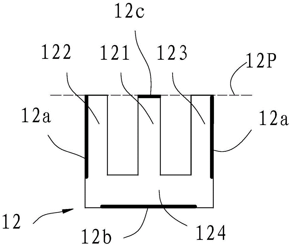
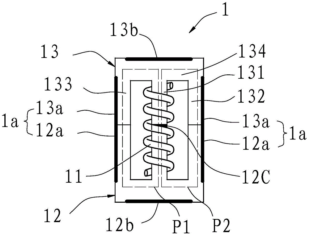
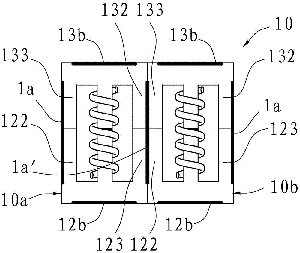
[0034] Please refer to figure 2 , image 3 . In this embodiment, the inductor assembly 2 includes two figure 2 The illustrated inductors are respectively marked as inductor 10a and inductor 10b for specific distinction. The central axes of the inductance coils 11 of the inductors 10a, 10b are parallel to each other. figure 1 , figure 2 The central axes of the inductance coils 11 of the middle inductors 10a and 10b both extend in the vertical direction. The side cylinders of the two inductors 10a and 10b are in contact, that is, the side column 132 of the inductor 10a is in contact with the side column 133 of the inductor 10b, and the side column 123 of the inductor 10a is in contact with the side column 122 of the inductor 10b. offset, and then closely arranged into a 1×2 rectangular array. At the position where the outer sides of the magnetic cores 12 of the two adjacent inductors 10a, 10b meet, the air gap 1a of the inductor 10a and the air gap 1a of the inductor 10...
no. 2 example
[0040] Please refer to image 3 and Figure 4 . Compared with the inductor assembly of the first embodiment, the inductor assembly in this embodiment further includes a fixing plate 14 and four conductive inserts 16a, 16b, 16c and 16d vertically fixed on the fixing plate 14 . Wherein, the fixing plate 14 is packaged together with the inductor 10 , that is, the fixing plate 14 and the inductor 10 are fixed by the filling material 15 . The filling material 15 can be selected from resin material, such as polypropylene material, and the material of the fixing plate 14 can be selected from phenolic resin. Wherein, the conductive insert 16a is electrically connected to one end of the inductance coil 11 of the inductor 10b, and the conductive insert 6b is electrically connected to the other end of the inductance coil 11 of the inductor 10b; the conductive insert 16c is electrically connected to one end of the inductance coil 11 of the inductor 10a , the conductive insert 16d is el...
no. 3 example
[0043] Please refer to figure 2 , image 3 , Figure 5 . In this embodiment, the difference from the first embodiment is that the inductor assembly 10 in this embodiment further includes two figure 2 The shown inductors are respectively marked as inductors 10c and 10d for ease of distinction.
[0044] Among these four inductors, the relative positional relationship of the inductors 10c and 10d is exactly the same as that of the inductors 10a and 10b in the second embodiment. In this embodiment, the bottom post 124 of the inductor 10a is in contact with the bottom post 134 of the inductor 10c, and the air gap 12b of the inductor 10a is opposite to the air gap 13b of the inductor 10c. The extension direction of the air gap 13b together forms a new air gap 1b. Similarly, the relative positional relationship of the inductors 10b, 10d is exactly the same as that of the inductors 10a, 10c, that is, the bottom column 124 of the inductor 10c is in contact with the bottom column...
PUM
 Abstract
Description
Claims
Application Information
 - R&D Engineer
- R&D Manager
- IP Professional
- Industry Leading Data Capabilities
- Powerful AI technology
- Patent DNA Extraction
Browse by: Latest US Patents, China's latest patents, Technical Efficacy Thesaurus, Application Domain, Technology Topic, Popular Technical Reports.
© 2024 PatSnap. All rights reserved.Legal|Privacy policy|Modern Slavery Act Transparency Statement|Sitemap|About US| Contact US: help@patsnap.com


