
Workpiece basket clamping and rotating device

A technology of rotating device and basket card, which is applied to the device and coating of the surface coating liquid, which can solve the defects, cannot completely ensure the simultaneous clamping and loosening of the workpiece basket, and increase the workload of the staff, etc.

Inactive Publication Date: 2016-06-29
CHANGZHOU JUNHE TECH
View PDF8 Cites 1 Cited by
  • Summary
  • Abstract
  • Description
  • Claims
  • Application Information

AI Technical Summary

Problems solved by technology

[0002] During the workpiece coating process, the workpiece needs to be loaded into the workpiece basket, soaked by putting the workpiece basket into the coating liquid tank, and after the soaking is completed, the excess coating liquid on the surface of the workpiece is dried; the existing workpiece basket is mostly It is very inconvenient to assemble and remove the workpiece basket in the way of bolt connection, which reduces the work efficiency and increases the workload of the staff; in addition, there are also clamping devices to fix the workpiece basket. Assembling, however, due to structural design defects, the existing clamping device takes up a large space and cannot completely guarantee the simultaneous clamping and loosening of the workpiece basket, which affects work efficiency and use effect

Method used


Image

  • Workpiece basket clamping and rotating device
  • Workpiece basket clamping and rotating device

Examples


Embodiment Construction

[0021] In order to make the purpose, technical solutions and advantages of the embodiments of the present invention more clear, the following will clearly and completely describe the technical solutions of the embodiments of the present invention in conjunction with the drawings of the embodiments of the present invention. Apparently, the described embodiments are some, not all, embodiments of the present invention. Based on the described embodiments of the present invention, all other embodiments obtained by persons of ordinary skill in the art without creative efforts shall fall within the protection scope of the present invention.

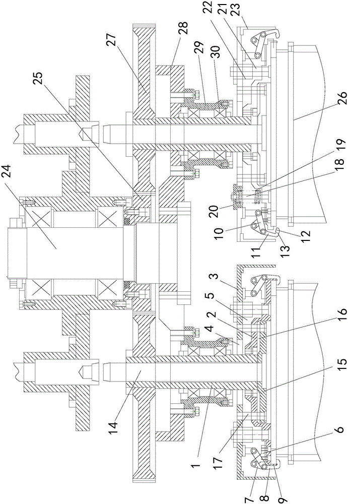
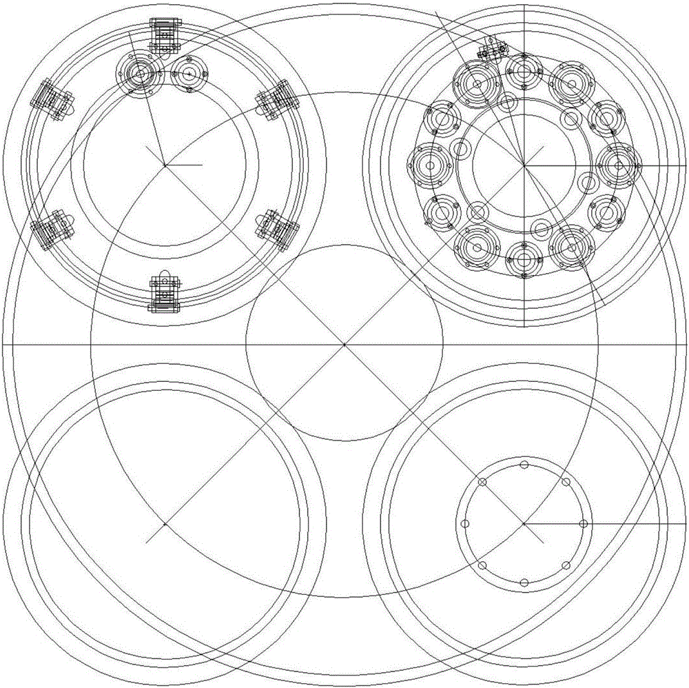
[0022] see figure 1 , 2 , the workpiece basket clamping and rotating device, including a hollow shaft 1, a positioning plate 2 sleeved on one end of the rotating shaft and rotating with the shaft, and a pressing plate 3 sleeved on the rotating shaft above the positioning disc, and the positioning disc passes through screws or bolts Or welding ...


PUM


Abstract

The invention discloses a workpiece basket clamping and rotating device in a coating machine, which comprises a hollow rotating shaft, a positioning plate sleeved on one end of the rotating shaft and rotated with the rotating shaft, and a pressing plate sleeved on the rotating shaft above the positioning plate , there are several pressing mechanisms arranged between the positioning plate and the pressing plate, which include a claw seat fixed on the positioning plate, a pressing claw set on the claw seat through a linkage arm, and one end of the pressing claw is connected to the The pressing plate is connected, and a pressing space is formed between the other end of the pressing claw and the lower surface of the positioning plate, and the ejector rod is installed in the rotating shaft. One end of the ejector rod is provided with a top plate, and the top plate is located below the lower surface of the positioning plate. The top plate and the pressing plate are connected as a whole by a connecting device, and an elastic device compressed by the positioning plate and the pressing plate is arranged between the positioning plate and the pressing plate. Compared with the previous clamping device, the present invention is optimized in structure, occupies less space, ensures the clamping force on the workpiece basket, and improves the clamping efficiency of the workpiece basket.

Description

technical field [0001] The invention relates to the technical field of coating equipment, in particular to a workpiece basket clamping and rotating device used in coating equipment. Background technique [0002] During the workpiece coating process, the workpiece needs to be loaded into the workpiece basket, soaked by putting the workpiece basket into the coating liquid tank, and after the soaking is completed, the excess coating liquid on the surface of the workpiece is dried; the existing workpiece basket is mostly It is very inconvenient to assemble and remove the workpiece basket in the way of bolt connection, which reduces the work efficiency and increases the workload of the staff; in addition, there are also clamping devices to fix the workpiece basket. Assembling, however, due to structural design defects, the existing clamping device takes up a large space and cannot completely guarantee the simultaneous clamping and loosening of the workpiece basket, which affects ...

Claims


Application Information

Patent Timeline
Patent Type & Authority Applications(China)
IPC IPC(8): B05C13/00
CPCB05C13/00
Inventor 钱永键吴伟峰吴昊
Owner CHANGZHOU JUNHE TECH
Learn More