Boiler flue gas cleaning waste heat recycling device

A waste heat recovery device and flue gas purification technology, which is applied in the direction of circuit devices, battery circuit devices, electrical components, etc., can solve problems such as heat energy loss, and achieve the effect of dust removal and waste heat reuse

Active Publication Date: 2016-06-29
桃源县泰香粮油科技开发有限公司
View PDF6 Cites 1 Cited by
  • Summary
  • Abstract
  • Description
  • Claims
  • Application Information

AI Technical Summary

Problems solved by technology

[0002] The flue gas of the boiler contains a lot of dust and heat energy. In the prior art, the flue gas is usually passed through the condensing tower and sprayed to remove the dust. However, the cold water that is usually sprayed will lose heat energy after spraying; how to remove dust after spraying? While ensuring the recovery and reuse of waste heat, it is worth exploring

Method used


Image

  • Boiler flue gas cleaning waste heat recycling device
  • Boiler flue gas cleaning waste heat recycling device
  • Boiler flue gas cleaning waste heat recycling device

Examples


Embodiment Construction

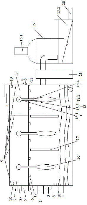
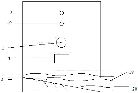
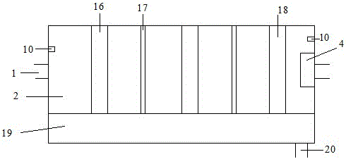
[0017] In order to increase dust removal efficiency and waste heat recovery and utilization, the present invention proposes a boiler flue gas purification waste heat recovery device.

[0018] This waste heat recovery device for filtering flue gas purification includes a boiler air outlet 1, which is characterized in that the upper closed water pool 2 is connected to the boiler air outlet 1, and a PLC controller 3 is installed on the outer wall of the water pool 2 under the boiler air outlet 1 The top of the pool 2 has a storage battery 4; the top of the pool 2 is a thermal insulation layer 5; the bottom of the thermal insulation layer 5 is connected with a heat conducting plate 6; the thermal conducting plate 6 and the heat insulating layer 5 form a first closed space 7; the first closed space 7 There is a water inlet 8 and a water outlet 9 outside the left side; there is an inductor 10 in the left side of the first closed space 7; a heat shield 11 is installed next to the heat...


PUM


Abstract

A boiler flue gas cleaning waste heat recycling device comprises a boiler air outlet.The boiler flue gas cleaning waste heat recycling device is characterized in that a water tank with the sealed upper portion is connected with the boiler air outlet, a programmable logic controller (PLC) is positioned below the boiler air outlet and installed on the outer wall of the water tank, and the top of the water tank is provided with a storage battery.The top of the water tank is provided with a heat insulation layer, and the lower portion of the heat insulation layer is connected with a heat conduction plate.The heat conduction plate and the heat insulation layer form a first sealed space.A water inlet and a water outlet are positioned outside the left side of the first sealed space, a sensor is positioned in the left side of the first sealed space, and a heat insulation plate is installed beside the heat conduction plate.A spraying nozzle is installed below the heat insulation plate.The heat insulation plate and the heat insulation layer form a second sealed space, and a water inlet and a water outlet are positioned outside the right side of the second sealed space.The boiler flue gas cleaning waste heat recycling device has the advantage that flue gas dedusting and waste heat reuse are achieved.

Description

technical field [0001] The invention belongs to the field of boiler work, in particular to a boiler flue gas purification waste heat recovery device. Background technique [0002] The flue gas of the boiler contains a lot of dust and heat energy. In the prior art, the flue gas is usually passed through the condensing tower and sprayed to remove the dust. However, the cold water usually sprayed will lose heat energy after spraying; how to remove dust after spraying? While ensuring the recovery and reuse of waste heat, it is worth exploring. Contents of the invention [0003] In order to increase dust removal efficiency and waste heat recovery and utilization, the present invention proposes a boiler flue gas purification waste heat recovery device. [0004] This waste heat recovery device for filtering flue gas purification includes a boiler air outlet, which is characterized in that the upper closed pool is connected to the boiler air outlet, a PLC controller is installed ...

Claims


Application Information

Patent Timeline
Patent Type & Authority Applications(China)
IPC IPC(8): B01D47/06H02J7/32H02N11/00
CPCB01D47/06H02J7/32H02N11/002
Inventor 袁万胜
Owner 桃源县泰香粮油科技开发有限公司
Why Eureka
Try Eureka