Control devices for internal combustion engines

A technology for a control device and an internal combustion engine, which is applied to fuel injection devices, internal combustion piston engines, and coolant flow control, etc., can solve the problems of heat increase and the length of time required for engine warm-up to increase, and achieve the effect of shortening the length of time.

Inactive Publication Date: 2018-07-06
TOYOTA JIDOSHA KK
View PDF5 Cites 0 Cited by
  • Summary
  • Abstract
  • Description
  • Claims
  • Application Information

AI Technical Summary

Problems solved by technology

Therefore, during warm-up of the internal combustion engine, for example, when heat dissipation from cooling water circulating through the LT intercooler to the atmosphere is performed, heat transfer from the HT intercooler to the LT intercooler may increase, and engine warm-up requires length of time may increase

Method used


Image

  • Control devices for internal combustion engines
  • Control devices for internal combustion engines
  • Control devices for internal combustion engines

Examples


Embodiment Construction

[0037] first embodiment. A first embodiment of the present invention will be described with reference to the drawings.

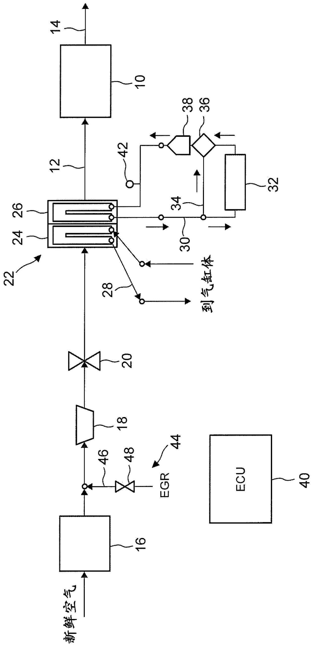
[0038] [Configuration of the first embodiment] figure 1 is a diagram showing the system configuration of the control device according to the present embodiment. The control device according to the present embodiment includes an internal combustion engine 10 . The internal combustion engine 10 is configured as a four-stroke reciprocating engine provided with a turbocharger. An intake passage 12 and an exhaust passage 14 communicate with each cylinder of the internal combustion engine 10 . In the intake passage 12 , a compressor 18 of the turbocharger is arranged on the downstream side of the air cleaner 16 . The turbocharger is provided with a turbine (not shown) which is operated by the exhaust energy of the exhaust gas in the exhaust passage 14 . The compressor 18 is integrally connected to the turbine via a connection shaft, and is driven to rotate ba...


PUM


Abstract

The invention relates to a control device for an internal combustion engine. An internal combustion engine has a water-cooled intercooler that cools an intake air that is turbocharged by a turbocharger. The intercooler has an HT intercooler and an LT intercooler, the HT cooling water passing through the cylinder block is introduced into the HT intercooler, and the LT cooling water having a lower temperature than the HT cooling water is introduced into the LT cooler, and the LT intercooler is arranged adjacent to the intake air downstream side of the HT intercooler. In the case where the temperature of the HT cooling water flowing into the HT intercooler is lower than the target HT temperature associated with completion of warm-up, the target LT temperature is set as the high temperature side target value, and the HT cooling water In the case where the temperature of is equal to or higher than the target HT temperature, the target LT temperature is set as the low temperature side target value.

Description

technical field [0001] The invention relates to a control device for an internal combustion engine. Background technique [0002] For example, Japanese Patent Application Laid-Open No. 2001-248448 discloses an intake air cooling device that cools supply air in two stages by using two cooling cores through which cooling water flows. In this device, the first-stage cooling core on the upstream side of the supply air on which the high cooling water temperature is set and the second-stage cooling core on the supply air downstream side on which the low cooling water temperature is set form a cooling core built into the supply air supply. One-piece combination in the gas manifold. According to this configuration, the cooling water in the cylinder block is used as the high-temperature water of the first-stage cooling core, and thus the amount of heat recovery is increased and the overall efficiency is improved. In addition, the second-stage cooling core near the air supply port c...

Claims


Application Information

Patent Timeline
Patent Type & Authority Patents(China)
IPC IPC(8): F02B29/04F01P7/14
CPCF01P7/14F02B29/0406F01P7/165F02B29/0412F02B29/0443F02B29/0493F01P3/20F01P2060/02F02M21/0248F02M21/04Y02T10/12F02B29/04F01P7/167F01P2060/12F02M51/061F02M61/18F02M63/0015F02M26/04F02M26/32
Inventor 冈田吉弘
Owner TOYOTA JIDOSHA KK
Why Eureka
Try Eureka