
An automatic equipment and method for high-speed laser marking and blanking and packaging

An automated equipment and laser marking technology, applied in packaging, typewriters, printing, etc., can solve the problems of limited conveyor belt transmission speed, impractical mass production of nuts, and inability to achieve high-speed marking, etc., to achieve accurate counting, counting High precision, anti-rolling effect

Active Publication Date: 2018-02-23
EC PRECISION TECHJIANGSUCORP
View PDF6 Cites 0 Cited by
  • Summary
  • Abstract
  • Description
  • Claims
  • Application Information

AI Technical Summary

Problems solved by technology

[0002] The existing nuts are packaged directly after the production and processing are completed, and no labeling will be carried out. However, with the improvement of customer requirements, it is imperative to carry out labeling on the nuts. The labeling process on the nuts is to use laser on the side of the nuts. Print the corresponding identification symbols. The most common identification method at this stage is to manually mark the nuts one by one with a laser marker. This method is fine for small batches, but it is impractical for large batches of nuts. Yes, in order to solve this situation, there has been a single-row marking method for the conveyor belt. Put the nuts flat on the conveyor belt and mark them one by one from the side through the laser head. Compared with manual marking It saves a lot of manpower and time, but this method needs to detect whether there is a nut through the detector first, and the transmission speed of the conveyor belt is limited, so high-speed marking cannot be achieved

Method used


Image

  • An automatic equipment and method for high-speed laser marking and blanking and packaging
  • An automatic equipment and method for high-speed laser marking and blanking and packaging
  • An automatic equipment and method for high-speed laser marking and blanking and packaging

Examples


no. 1 example

[0045] Such as Figure 2-6 As shown, the blanking mechanism 3 includes a mounting plate 9, a Y-shaped nylon slide rail 10 installed on the mounting plate 9, a first material stop mechanism 11, a second material stop mechanism 12, and a third material stop mechanism 13 , the fourth blocking mechanism 14, the fifth blocking mechanism 15, the sixth blocking mechanism 16, the seventh blocking mechanism 17, the first clamping mechanism 18, the second clamping mechanism 19 and the counting storage mechanism 20, wherein:

[0046] The upper end surface of the mounting plate 9 is a smooth surface of stainless steel, and the side is provided with a concave height adjustment groove 27 .

[0047] The Y-shaped nylon slide rail 10 is composed of a first feeding slide rail 21, a second feeding slide rail 22, a first buffer slide rail 24, a second buffer slide rail 25 and a blanking slide rail 23, wherein the first upper One end of the material slide rail 21 is connected to an outlet of the ...

Embodiment 2

[0058] Such as Figure 7-9 As shown, the technical difference between this embodiment and embodiment 1 lies in the Y-type nylon slide rail. In the present embodiment, the Y-type nylon slide rail 10 is composed of the first feeding slide rail 21 ', the second feeding slide rail 22', and the second feeding slide rail 22'. A buffer slide rail 24', a second buffer slide rail 25' and a blanking slide rail 23', wherein one end of the first feeding slide rail 21' is connected to an outlet of the vibrating plate, and the other end is connected to the first buffer slide rail 24' After that, it is connected to the unloading slide rail 23'. One end of the second loading slide rail 22' is connected to the other outlet of the vibrating plate, and the other end is connected to the second buffer slide rail 25' and then connected to the unloading slide rail 23'.

[0059] The first feeding slide rail 21' is composed of a first left baffle 211' and a first right baffle 212', and the first left ...


PUM


Abstract

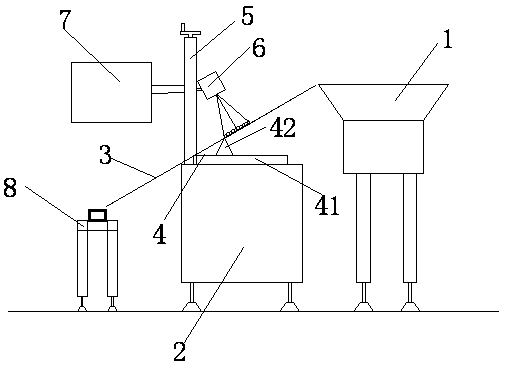
The invention discloses automatic equipment and method for achieving high-speed laser marking and discharging packaging. The automatic equipment comprises a vibration disc, a control cabinet, a discharging sliding rail, a height adjusting mechanism, a mounting column, a laser marking head, a displayer and a conveying mechanism. The discharging sliding rail is obliquely mounted above the control cabinet through the height adjusting mechanism. The mounting column is mounted on the control cabinet. The laser marking head and the displayer are mounted on the mounting column. The vibration disc is arranged at the high end of the discharging sliding rail. The conveying mechanism is mounted at the lower end of the discharging sliding rail. According to the automatic equipment for achieving high-speed laser marking and discharging packaging, automatic feeding, automatic marking, automatic counting and discharging packaging of nuts are combined together, meanwhile marking is conducted in a double-row manner, and high-speed marking can be achieved effectively.

Description

technical field [0001] The invention relates to an automation equipment for fasteners, in particular to an automation equipment and method for high-speed laser marking and blanking and packaging. Background technique [0002] The existing nuts are packaged directly after the production and processing are completed, and no labeling will be carried out. However, with the improvement of customer requirements, it is imperative to carry out labeling on the nuts. The labeling process on the nuts is to use laser on the side of the nuts. Print the corresponding identification symbols. The most common identification method at this stage is to manually mark the nuts one by one with a laser marker. This method is fine for small batches, but it is impractical for large batches of nuts. Yes, in order to solve this situation, there has been a single-row marking method for the conveyor belt. Put the nuts flat on the conveyor belt and mark them one by one from the side through the laser hea...

Claims


Application Information

Patent Timeline
Patent Type & Authority Patents(China)
IPC IPC(8): B41J2/455B41J3/407B65B63/00B65B35/30
CPCB65B35/30B65B63/00
Inventor 朱叶曹淦琛
Owner EC PRECISION TECHJIANGSUCORP
Learn More