
A radiograph marking machine and marking method

A radiographic and marking machine technology, applied in the field of radiographic inspection, can solve the problems of high filming error rate and low productivity, and achieve the effects of simple structure, low cost and improved production rate

Active Publication Date: 2018-09-14
SHANGHAI BOILER WORKS
View PDF10 Cites 0 Cited by
  • Summary
  • Abstract
  • Description
  • Claims
  • Application Information

AI Technical Summary

Problems solved by technology

[0003] For the marking of the drawing number and order number of radiographs, the lead photo imaging method is still widely used in China to mark the drawing number and order number. This method has low productivity, so the rate of filming errors caused by this method is also high.

Method used


Image

  • A radiograph marking machine and marking method
  • A radiograph marking machine and marking method
  • A radiograph marking machine and marking method

Examples


Embodiment Construction

[0026] Below in conjunction with specific embodiment, further illustrate the present invention. It should be understood that these examples are only used to illustrate the present invention and are not intended to limit the scope of the present invention. In addition, it should be understood that after reading the teachings of the present invention, those skilled in the art can make various changes or modifications to the present invention, and these equivalent forms also fall within the scope defined by the appended claims of the present application.

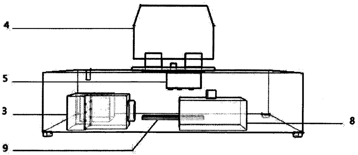
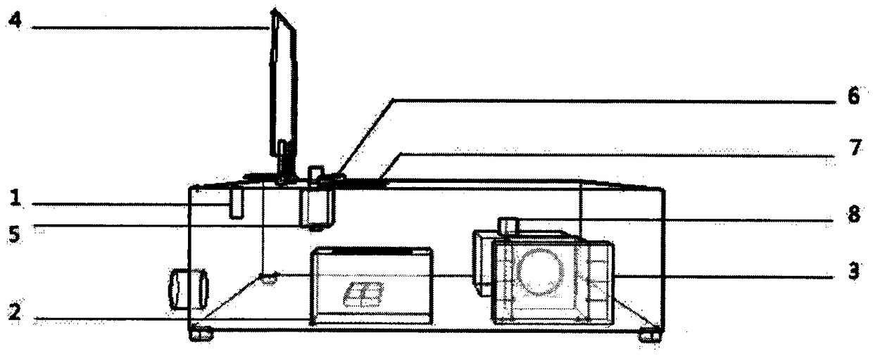
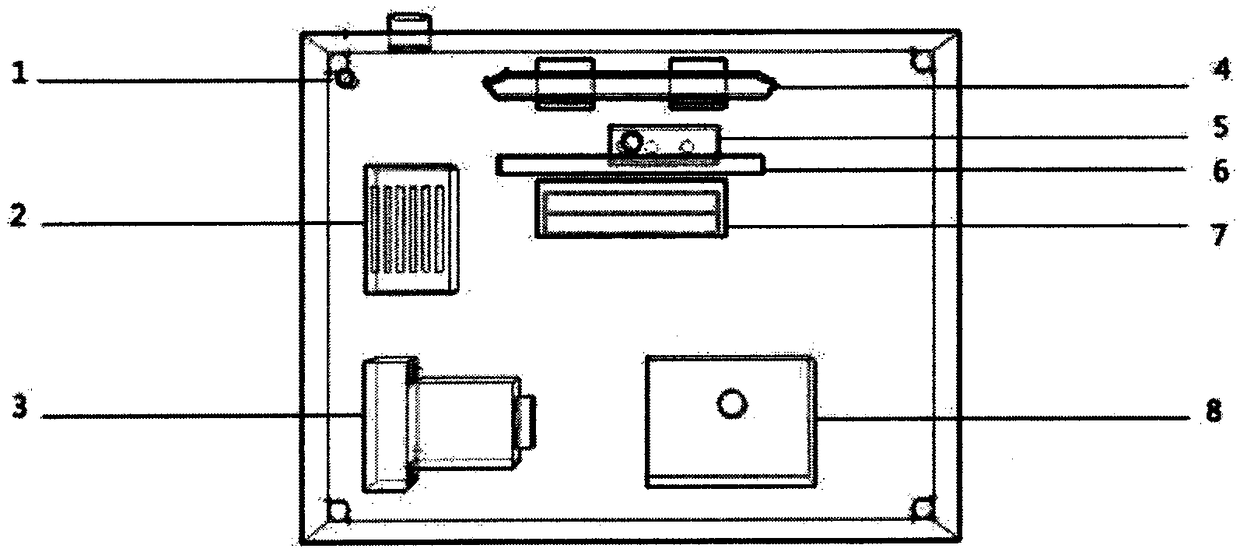
[0027] Figure 1 ~ Figure 3 They are the front view, side view, and top view of the radiograph marking machine provided in this embodiment, respectively. The radiograph marking machine is composed of a signal lamp 1, a transformer 2, a time relay 3, a spring pressure plate 4, a micro switch 5, and a positioning bar 6. Composed of exposure screen 7, dimmer 8, LED exposure lamp 9, etc.

[0028] The 220V power supply is connecte...


PUM


Abstract

The invention provides a radiogram marking machine and marking method. The radiogram marking machine comprises a transformer used for converting high-voltage alternating current into low-voltage direct current; two ends of the transformer are respectively connected with a power supply and a microswitch; the microswitch is connected with a time relay; the time relay is connected with a light modulator; the light modulator is connected with a LED exposure lamp and a signal lamp; an exposure screen is arranged to face the LED exposure lamp; and one side of the exposure screen is provided with a spring bearer plate used for positioning a marking scope and triggering the microswitch. The invention also provides a radiogram marking method. According to the method, a radiographic testing photograph having undergone exposure is subjected to secondary exposure to visible light so as to mark the photograph with a marking; after exposure to rays, the photograph still has unreacted ions; and the exposure screen gives off character-shape light rays to irradiate the film base of the photograph, so compounding of the unreacted ions is promoted and imaging is realized so as to accomplish marking of the photograph. The radiogram marking machine provided by the invention is simple in structure, convenient to install and maintain and low in price, and improves the production efficiency of ray detection and the automation level of flaw detection.

Description

technical field [0001] The invention relates to a radiograph marking machine and a marking method, belonging to the technical field of radiation detection. Background technique [0002] Radiographic testing is one of the most important non-destructive testing methods, which provides an intuitive and reliable basis for product quality. Radiographic testing is also a nondestructive testing method with high testing cost and low testing speed among the existing nondestructive testing methods. Residual unreacted ions after radiographic flaw detection exposure can be subjected to a second exposure. [0003] For the marking of the drawing number and order number of radiographs, the lead photo imaging method is still widely used in China to mark the drawing number and order number. This method has low productivity, so the rate of filming errors caused by this method is also high. Contents of the invention [0004] The technical problem to be solved by the present invention is ho...

Claims


Application Information

Patent Timeline
Patent Type & Authority Patents(China)
IPC IPC(8): G03F7/20
CPCG03F7/70008G03F7/70516G03F7/7055
Inventor 黄晨宇庄升平
Owner SHANGHAI BOILER WORKS
Learn More