
Endoscope device

An endoscope and lens technology, applied in the field of endoscope devices with automatic focusing function, can solve the problems of image quality degradation, narrow depth of field, etc., and achieve the effect of improving the accuracy of automatic focusing and high-precision focusing

Active Publication Date: 2016-06-15
OLYMPUS CORP
View PDF9 Cites 7 Cited by
  • Summary
  • Abstract
  • Description
  • Claims
  • Application Information

AI Technical Summary

Problems solved by technology

In such an endoscope device, when the aperture of the optical system is stopped down too much in order to ensure the depth of field, the image quality of the acquired image is degraded due to diffraction limit
On the other hand, when the aperture cannot be stopped down, the depth of field becomes narrower

Method used


Image

  • Endoscope device
  • Endoscope device
  • Endoscope device

Examples


Embodiment Construction

[0031] Hereinafter, an endoscope device according to an embodiment of the present invention will be described with reference to the drawings.

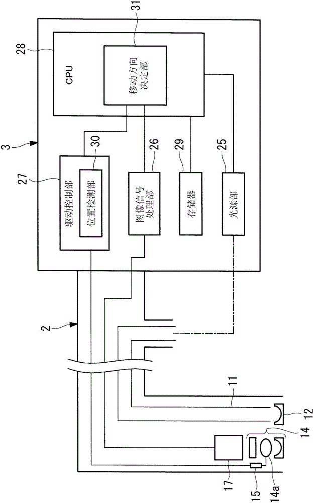
[0032] Such as figure 1 As shown, the endoscope apparatus includes: an elongated insertion part 2, which is inserted into the subject; and an endoscope control part 3, which performs the supply of illumination light to the insertion part 2 or Various controls such as obtaining the observed image of the subject.

[0033] A light guide member 11 for guiding illumination light penetrates through the insertion portion 2 . An illumination lens 12 for emitting illumination light toward a subject is provided on the front end side of the light guide member 11 , and the base end side of the light guide member 11 is connected to a light source unit 25 described later via a cable and a connector (not shown). Accordingly, the subject is irradiated with the illumination light emitted from the light source unit 25 via the light guide member 11 an...


PUM


Abstract

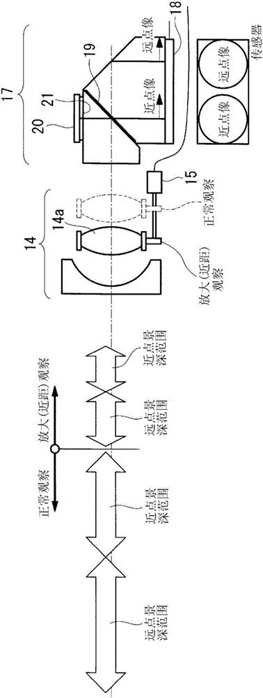
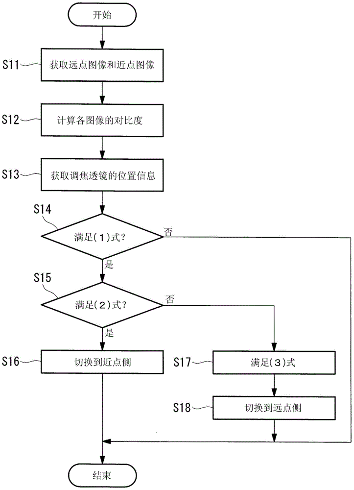
An objective of the present invention is to allow simplification of an assessment of a determination of a direction of movement of a focusing lens, and to improve auto-focusing precision. Provided is an endoscope device, comprising: an optical assembly (14), further comprising a focusing lens (14a); a lens drive means (15) for moving the focusing lens in the optical axis direction and switching the observation depth; an image capture means (17) for acquiring optical images of a subject via the optical assembly as a plurality of images with respectively different focal locations; a movement direction determination means (31) for assessing, on the basis of the plurality of images, whether it is necessary to switch the observation depth, and if it is assessed that it is necessary to switch the observation depth, for determining the direction of movement of the focusing lens on the basis of the images; and a drive control means (27) for controlling the lens drive means to move the focusing lens in the determined direction of movement.

Description

technical field [0001] The invention relates to an endoscope device, in particular to an endoscope device with an automatic focusing function. Background technique [0002] Conventionally, in an endoscope device, an imaging element with a low number of pixels is used for downsizing the device, and an image with a sufficiently wide depth of field can be acquired only by reducing the aperture of the optical system. [0003] In recent years, the finer pixelation of imaging elements has progressed, and more detailed observation and diagnosis can be performed by applying imaging elements with a large number of pixels to endoscope devices. In such an endoscope device, when the aperture of the optical system is stopped down too much in order to ensure the depth of field, the image quality of the acquired image is degraded due to diffraction limit. On the other hand, when the aperture cannot be stopped down, the depth of field becomes narrow. Therefore, various endoscope apparatus...

Claims


Application Information

Patent Timeline
Patent Type & Authority Applications(China)
IPC IPC(8): A61B1/00A61B1/04G02B7/28G02B23/24G02B23/26
CPCG02B23/26A61B1/00096A61B1/045A61B1/05G02B7/38G02B23/243A61B5/065A61B1/00188A61B1/00006A61B1/04H04N23/555H04N23/673A61B1/00133A61B5/06
Inventor 金野光次郎谷内章一
Owner OLYMPUS CORP
Learn More