
Method and device for laser-assisted autofocus

A laser-assisted, focusing position technology, applied in the direction of focusing devices, optics, color TV components, etc., can solve problems such as the inability to achieve laser-assisted focusing, meet the needs of laser-assisted autofocus, enhance user experience, and improve accuracy degree of effect

Active Publication Date: 2019-04-12
YULONG COMPUTER TELECOMM SCI (SHENZHEN) CO LTD
View PDF4 Cites 0 Cited by
  • Summary
  • Abstract
  • Description
  • Claims
  • Application Information

AI Technical Summary

Problems solved by technology

However, the current focus position of laser-assisted focusing is the center of the display screen. When the focus position required by the user is not the center position, effective laser-assisted focusing cannot be achieved.

Method used


Image

  • Method and device for laser-assisted autofocus
  • Method and device for laser-assisted autofocus
  • Method and device for laser-assisted autofocus

Examples


Embodiment Construction

[0060] The technical solutions in the embodiments of the present invention will be clearly and completely described below in conjunction with the accompanying drawings in the embodiments of the present invention. Obviously, the described embodiments are only a part of the embodiments of the present invention, not all the embodiments. Based on the embodiments of the present invention, all other embodiments obtained by those of ordinary skill in the art without creative work shall fall within the protection scope of the present invention.

[0061] The following describes each embodiment separately.

[0062] The terms "first", "second", "third" and "fourth" in the specification and claims of the present invention and the above-mentioned drawings are used to distinguish different objects, rather than to describe a specific sequence. In addition, the terms "including" and "having" and any variations thereof are intended to cover non-exclusive inclusion. For example, a process, method, ...


PUM


Abstract

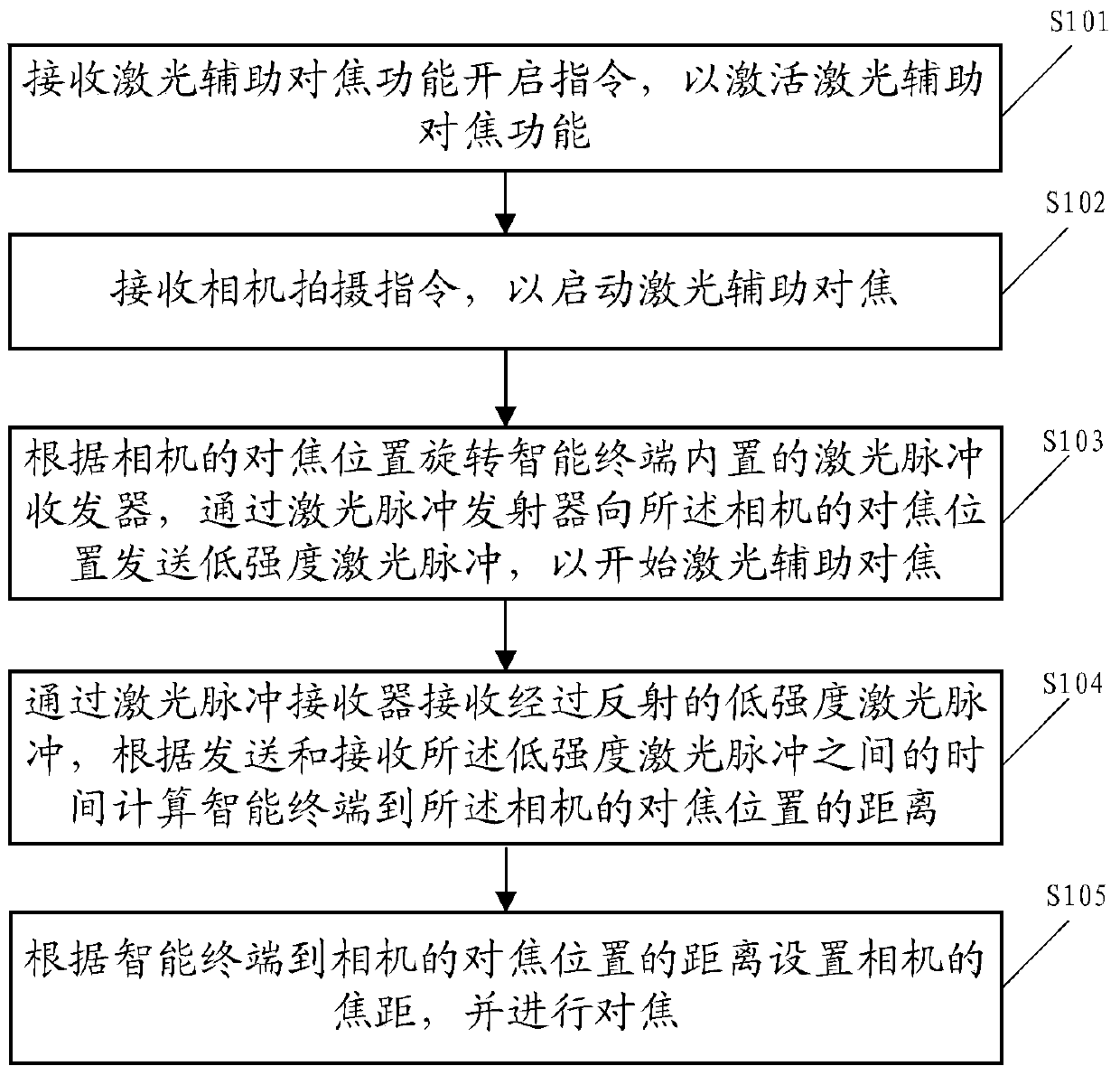
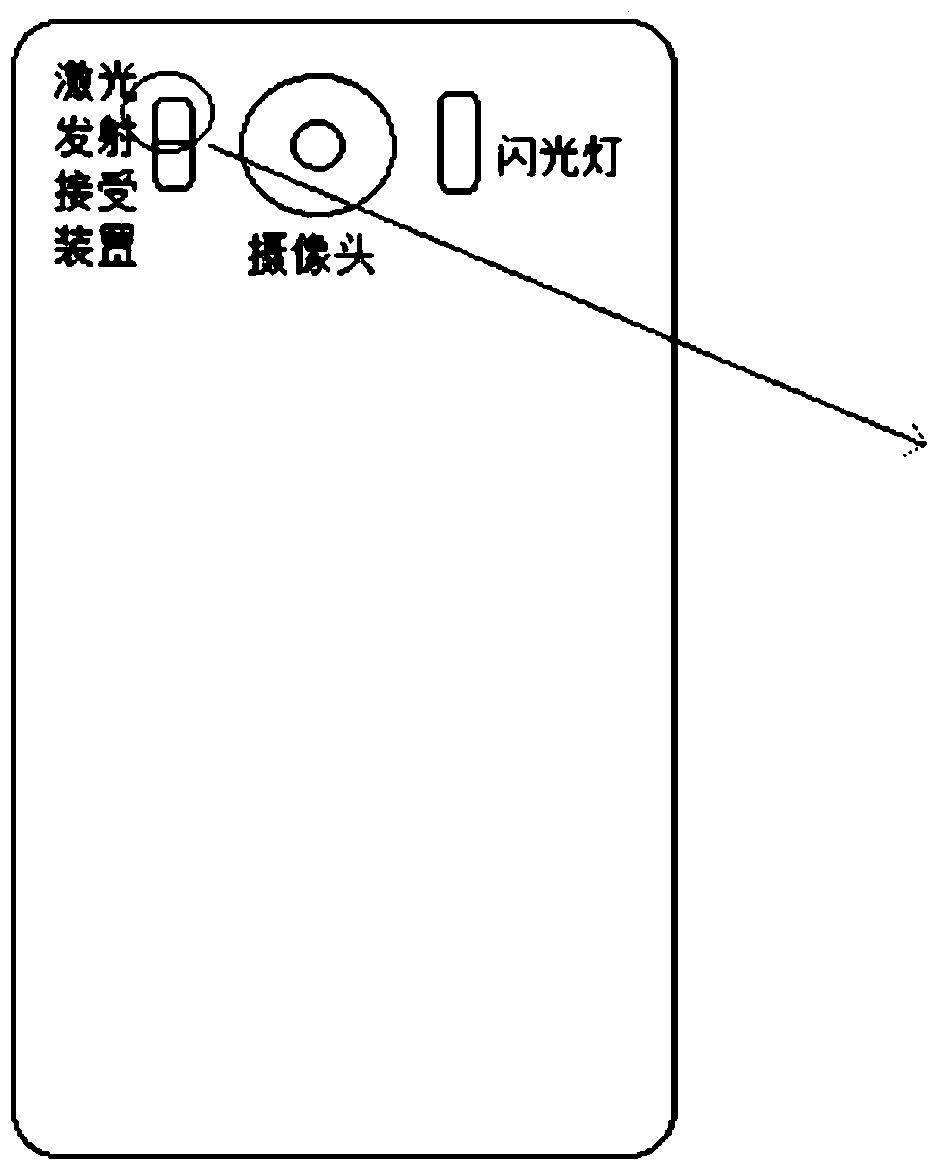
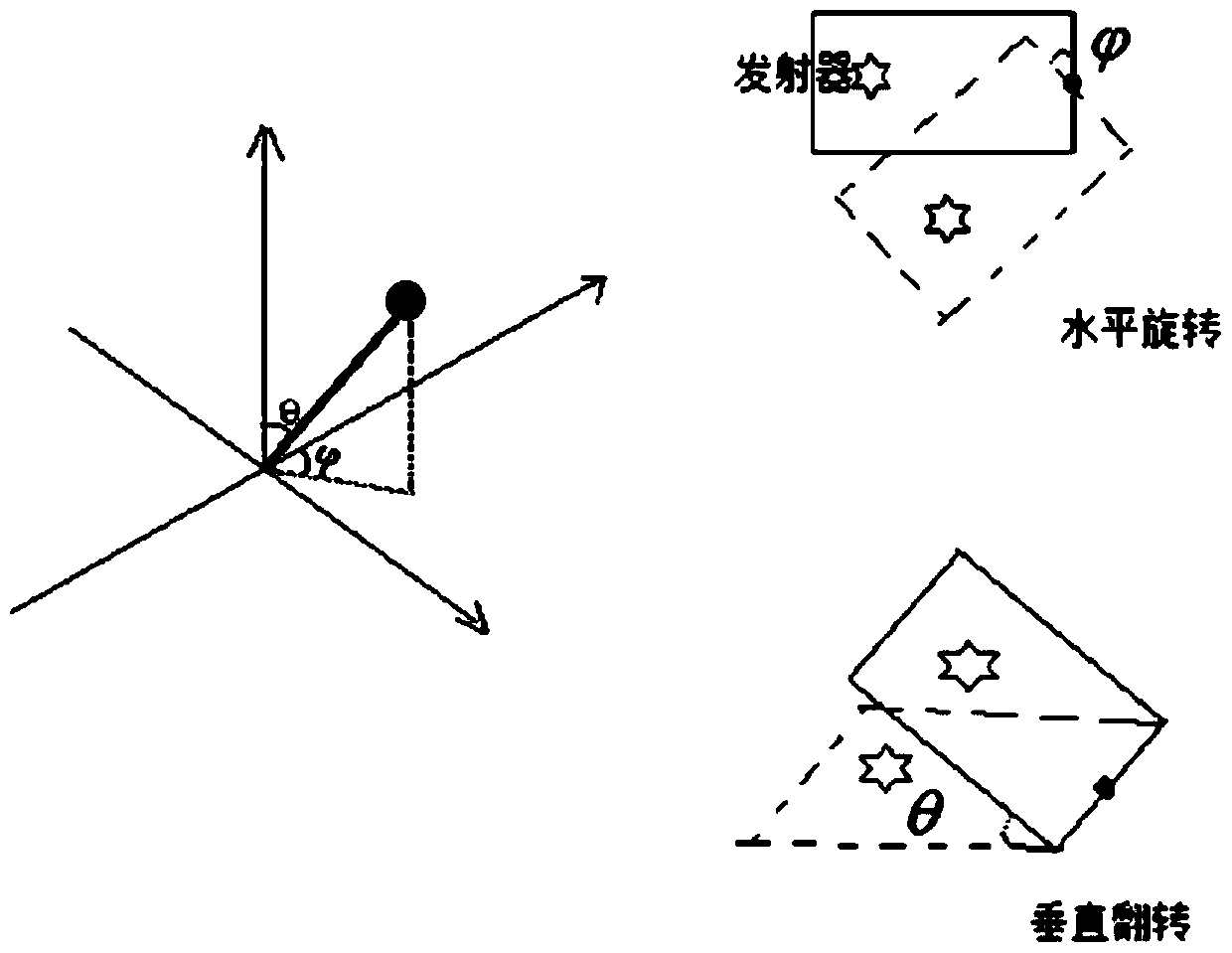
The embodiment of the present invention discloses a method for laser-assisted auto-focusing. The method includes: receiving an instruction to activate the laser-assisted focusing function to activate the laser-assisted focusing function; receiving a camera shooting instruction to start the laser-assisted focusing; Rotating the laser pulse transceiver, sending low-intensity laser pulses to the focus position of the camera through the laser pulse transmitter; receiving the reflected low-intensity laser pulses through the laser pulse receiver, according to sending and receiving the low-intensity laser pulses Calculate the distance between the smart terminal and the focus position of the camera; set the image distance of the camera and focus according to the distance from the smart terminal to the focus position of the camera. The technical solutions of the embodiments of the present invention can rotate the laser pulse transceiver according to the focus position required by the user, support laser-assisted auto-focus at different focus positions, improve the auto-focus accuracy of the smart terminal, and thereby improve user experience.

Description

Technical field [0001] The invention relates to the field of intelligent terminals, and in particular to a method and device for laser-assisted automatic focusing. Background technique [0002] With the popularization of mobile terminals, mobile devices such as mobile phones have become indispensable in life, and various additional functions of mobile devices have attracted more and more attention. In daily life, smart terminals have basically replaced card cameras. As people's photography tools. [0003] The autofocus of the smart terminal is different from the autofocus of the ordinary camera, and it cannot adjust the photosensitive element. Therefore, the auto focus function of the smart terminal is essentially based on the data calculation method of the image signal processor (ISP, Image Signal Processor), that is, when the viewfinder captures the original image, the image data is sent to the ISP as the original data. The ISP will analyze the raw data and check the density di...

Claims


Application Information

Patent Timeline
Patent Type & Authority Patents(China)
IPC IPC(8): H04N5/232G03B13/36G03B30/00
Inventor 蔡凤成吴超张斌
Owner YULONG COMPUTER TELECOMM SCI (SHENZHEN) CO LTD
Learn More