Tubular double-layer shunting structure microchannel-based heat exchange system

A heat exchange system and micro-channel technology, applied in electrical components, electric solid devices, circuits, etc., can solve the problem of affecting the stability and reliability of the device's operation, the heat dissipation technology cannot meet the heat dissipation requirements, and affect the working state of electronic devices. System stability And other issues

Active Publication Date: 2016-06-15
SOUTHEAST UNIV +1
View PDF5 Cites 0 Cited by
  • Summary
  • Abstract
  • Description
  • Claims
  • Application Information

AI Technical Summary

Problems solved by technology

[0002] With the rapid improvement of the operating speed and capacity of high-performance supercomputers and the continuous improvement of the performance requirements of missiles, military radars, laser weapons and other equipment on the performance of high-power devices, the integration of modern electronic devices continues to increase rapidly, and its local heat flux has increased. Up to nearly 1000 W / cm 2 , the traditional heat dissipation technology can no longer meet the heat dissipation requirements
The accumulation of heat in electronic devices will cause the temperature of devices and systems to rise rapidly, seriously affecting the working status of electronic devices and the stability of the system
Moreover, this type of device also puts forward new requirements for temperature uniformity. The uneven temperature of the device will affect the stability and reliability of the device, and may even cause device failure due to thermal stress

Method used


Image

  • Tubular double-layer shunting structure microchannel-based heat exchange system
  • Tubular double-layer shunting structure microchannel-based heat exchange system
  • Tubular double-layer shunting structure microchannel-based heat exchange system

Examples


Embodiment Construction

[0051] The present invention will be further described below in conjunction with accompanying drawing.

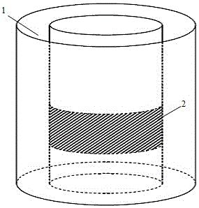
[0052] figure 1 A schematic diagram of a cylindrical small space applicable to the present invention is given. The cylindrical small space 1 is located between the walls of two cylinders and is cylindrical. The high heat flow annular cooling surface 2 is located on the inner wall surface. The invention is installed in the limited cylindrical space to dissipate heat on the annular cooling surface.

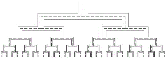
[0053] figure 2 The structure diagram of the microfluidic channel with the characteristics of the topological network is given. The microchannel of the split flow structure requires at least 3 stages, and each stage of the channel is divided into two. With the increase of the topological series, the number of channels is correspondingly multiplied, and the transport and distribution of the fluid working medium from point to surface are realized. Each final channel solves th...


PUM


Abstract

The invention discloses a tubular double-layer shunting structure microchannel-based heat exchange system, which comprises a pressure-stabilizing high-pressure tank, a cold source device, a circulating pump and a tubular double-layer shunting structure microchannel heat sink, wherein the tubular double-layer shunting structure microchannel heat sink comprises an inner layer shunting structure microchannel, an outer layer shunting structure microchannel and an inner and outer layer connecting microchannel; a microchannel fluid inlet is formed in the inner layer shunting structure microchannel; a microchannel fluid outlet is formed in the outer layer shunting structure microchannel; and the inner layer shunting structure microchannel is communicated with the outer layer shunting structure microchannel through the inner and outer layer connecting microchannel. By the double-layer shunting microchannel structure, small-area segmentation of a large-area heat source is achieved; the problems of uniform distribution and collection of the fluid are solved; meanwhile, the temperature uniformity of a heat dissipation device is also ensured when efficient cooling and heat dissipation are achieved by a micro-bubble jet subcooled boiling technology and the cold source device; and the working safety, stability and reliability of high-power tiny components in a cylinder are ensured.

Description

technical field [0001] The invention belongs to the technical field of heat dissipation of electronic devices, and in particular relates to a heat dissipation device suitable for high heat flux density conditions in a cylindrical small space. Background technique [0002] With the rapid improvement of the operating speed and capacity of high-performance supercomputers and the continuous improvement of the performance requirements of missiles, military radars, laser weapons and other equipment on the performance of high-power devices, the integration of modern electronic devices continues to increase rapidly, and its local heat flux has increased. Up to nearly 1000 W / cm 2 , the traditional heat dissipation technology has been unable to meet the heat dissipation requirements. The accumulation of heat in electronic devices will cause the temperature of devices and systems to rise rapidly, seriously affecting the working status of electronic devices and the stability of the sys...

Claims


Application Information

Patent Timeline
IPC IPC(8): H01L23/367H01L23/427H01L23/473
CPCH01L23/3675H01L23/427H01L23/473
Inventor 陈永平邓梓龙曹建光陈钢王江
Owner SOUTHEAST UNIV
Why Eureka
Try Eureka