Eureka AIR delivers breakthrough ideas for toughest innovation challenges, trusted by R&D personnel around the world.

Acoustic emission positioning monitoring device and method for hydraulic fracturing fissure field of coal body containing gas

A technology of hydraulic fracturing and monitoring device, which is applied in the direction of material analysis, instrumentation and analysis of materials using sonic emission technology, can solve the problems of inaccuracy and incomplete monitoring of the fracturing range of the distribution law of hydraulic fracturing and fracture fields in coal seams, etc. To achieve the effect of convenient operation, rich in-situ stress simulation function and good air tightness

Active Publication Date: 2016-06-15
CHINA UNIV OF MINING & TECH
View PDF9 Cites 21 Cited by
  • Summary
  • Abstract
  • Description
  • Claims
  • Application Information

AI Technical Summary

Problems solved by technology

[0006] The purpose of the present invention is to provide an acoustic emission positioning monitoring device and method for gas-containing coal hydraulic fracturing fissure field, which is easy to operate, simple in method, comprehensive and accurate, and solves the problem of distribution law of coal seam hydraulic fracturing fissure field and fracturing range monitoring. comprehensive, imprecise questions

Method used


Image

  • Acoustic emission positioning monitoring device and method for hydraulic fracturing fissure field of coal body containing gas
  • Acoustic emission positioning monitoring device and method for hydraulic fracturing fissure field of coal body containing gas
  • Acoustic emission positioning monitoring device and method for hydraulic fracturing fissure field of coal body containing gas

Examples


Embodiment 1

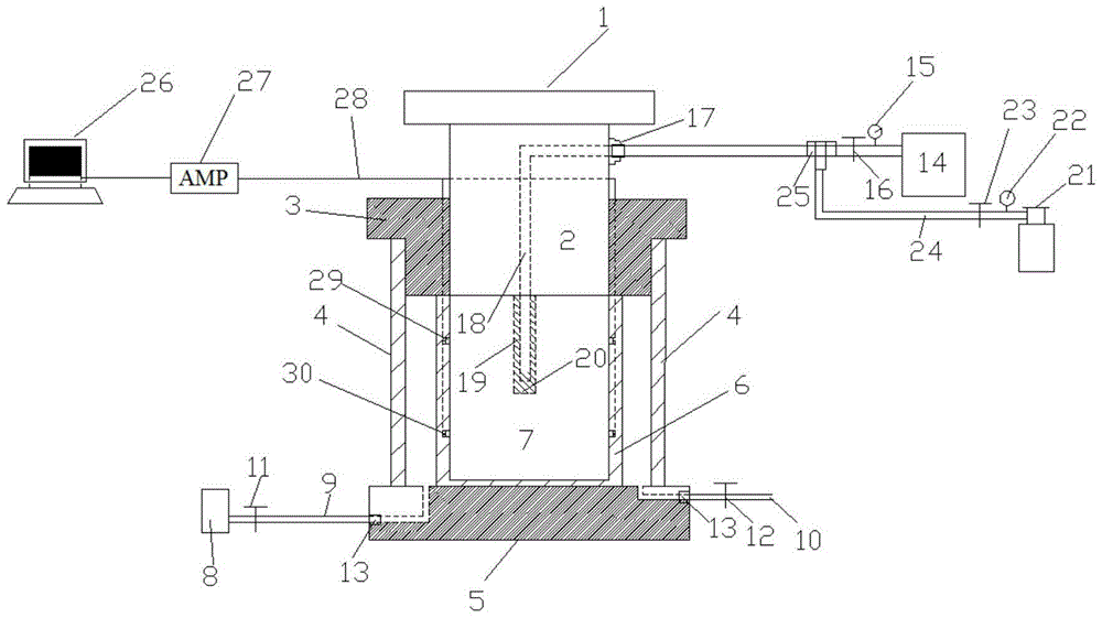
[0068] Embodiment 1: The first sealed cavity is surrounded by the base 5, the steel plate 4 on the base 5, the rubber tube 6 and the upper cover 3; The left channel and the right channel, the entrances of the left channel and the right channel are respectively provided with sealing bolts 13.

[0069] The second sealed chamber is in the first sealed chamber and is surrounded by a base 5, a rubber cylinder 6 with an open upper end surface on the base, an upper cover 3 and a plunger 2, and the upper cover 3 and the plunger 2 are sealed The ring is sealed.

[0070] The ground stress simulation module includes a loading press 1 and a plunger 2 for applying vertical pressure, an oil pump 8 for applying surrounding rock stress, a high-pressure oil pipe 9 and a drain pipe 10; the plunger 2 passes through the upper cover 3 and enters the second chamber In the body; the upper cover 3 of the first sealed cavity and the mating surface of the plunger 2 are provided with a sealing ring; on...


PUM

PropertyMeasurementUnit
diameteraaaaaaaaaa
heightaaaaaaaaaa
diameteraaaaaaaaaa

Abstract

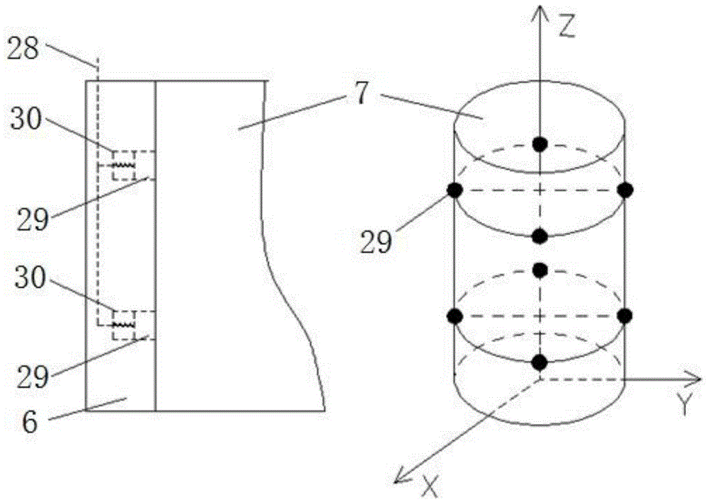
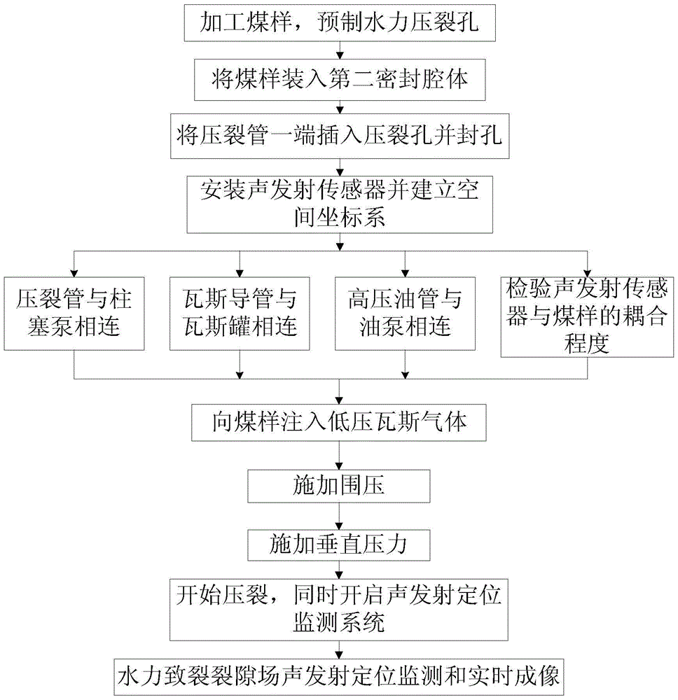
The invention provides an acoustic emission positioning monitoring device and method for a hydraulic fracturing fissure field of a coal body containing gas and belongs to a coal-mine gas disaster prevention and microseism monitoring device and method. The monitoring device is characterized in that a second sealing cavity body is connected in a first sealing cavity body; the two sealing cavity bodies are connected with a ground stress simulation module; a gas adsorption and desorption module is connected with a hydraulic fracturing module and then is connected with a plunger of the second sealing cavity body; a sensor of an acoustic emission positioning monitoring module is connected onto a wall of the second sealing cavity body. The method comprises steps as follows: the acoustic emission sensor is mounted, a coal sample is placed in the second sealing cavity body, and a space coordinates system is established; gas is injected into the coal sample and is sufficiently adsorbed by the coal sample; confining pressure and vertical pressure are applied to the coal sample; high pressure water with tracing color is injected into the coal body, an acoustic emission positioning monitoring system is started and is used for analyzing monitored acoustic emission signals and performing positioning monitoring on coal body fracturing incidents caused by hydraulic fracturing, and real-time monitoring for evolution of the hydraulic fracturing fissure field is realized.

Description

technical field [0001] The invention relates to a coal mine gas disaster prevention and microseismic monitoring device and method, in particular to a gas-containing coal body hydraulic fracturing fissure field acoustic emission positioning monitoring device and method. Background technique [0002] Coal is the main energy source in my country, accounting for about 70% of the primary energy structure. In recent years, many mining areas in my country have successively entered the deep mining area. Under the deep mining environment, the in-situ stress of the coal seam is large, the gas permeability of the coal seam is low, and the gas content and gas pressure increase significantly. The coal mine gas disaster is becoming more and more serious, and has become an important factor restricting the safe and efficient production of coal mines. [0003] Gas (coal bed methane) is not only a major source of danger in coal mines and a source of air pollution, but also a valuable non-ren...

Claims


Application Information

Patent Timeline
Patent Type & Authority Applications(China)
IPC IPC(8): G01N29/14
CPCG01N29/14G01N2291/023
Inventor 李楠陈栋李保林孙炜辰
Owner CHINA UNIV OF MINING & TECH
Why Eureka
Eureka Blog
Learn More