
Diagonal flow pump

A technology of oblique flow pump and pump shaft, which is applied in the direction of pumps, pump components, and parts of pumping devices for elastic fluids, etc. Large, increase the flow instability of the oblique flow pump, etc., to achieve the effect of reducing the back pressure gradient, reducing the peripheral velocity component of the incoming flow, and reducing the impact

Inactive Publication Date: 2016-06-15
JIANGSU UNIV
View PDF5 Cites 10 Cited by
  • Summary
  • Abstract
  • Description
  • Claims
  • Application Information

AI Technical Summary

Problems solved by technology

The tip leakage flow interacts with the mainstream to form a tip leakage vortex, which will not only affect the internal flow state of the mixed flow pump, but also block the flow channel and affect the operation stability of the mixed flow pump
Under the condition of small flow rate, the angle of attack at the blade inlet increases, and the fluid is easy to flow and separate at the blade inlet suction surface to form a vortex. The static pressure value will decrease rapidly, which will increase the pressure difference between the pressure surface and the suction surface, and the leakage of the tip of the blade will increase, thereby increasing the flow instability inside the inclined flow pump.
In addition, the leakage flow at the tip of the blade will increase the peripheral velocity component of the mainstream at the inlet rim of the adjacent blade, and the angle of attack at the inlet rim of the impeller will increase, causing the critical stall point of the mixed flow pump to shift to the direction of large flow, affecting the flow rate of the mixed flow pump. safe operation of

Method used


Image

  • Diagonal flow pump
  • Diagonal flow pump
  • Diagonal flow pump

Examples


Embodiment Construction

[0021] The present invention will be described in further detail below in conjunction with the accompanying drawings and specific embodiments.

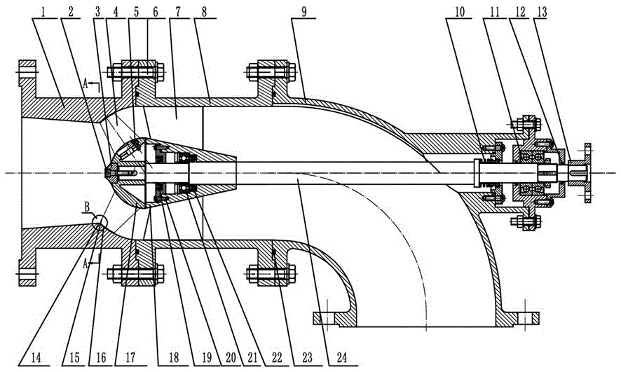
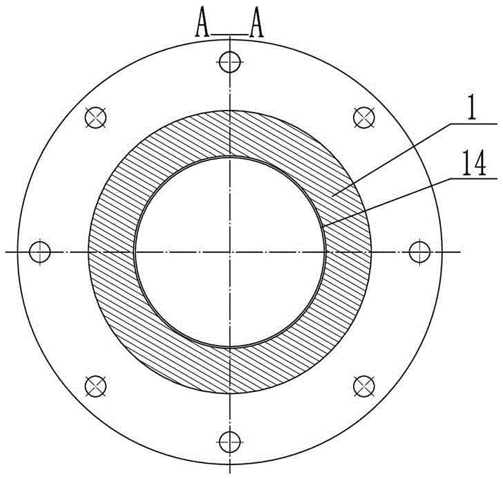
[0022] Depend on figure 1 figure 2 with image 3 It can be seen that the inclined flow pump is composed of an inlet section 1, a hexagon socket head screw 2, a water guide cone 3, a blade 4, a cylindrical head screw 5, a bolt 6, a guide vane 7, a cylindrical outer cylinder 8, and an elbow section 9 , mechanical seal 10, angular contact ball bearing 11, washer oil seal 12, coupling 13, annular groove 14, runner hub 17, guide vane body 18, bearing left oil seal 19, hexagon socket flat head screw 20, deep groove ball Bearing 21, bearing right oil seal 22; O-shaped sealing ring 23, pump shaft 24. The inlet section 1 is connected and fixed with the cylindrical outer cylinder 8 through the bolt 6, and the inlet section 1 and the cylindrical outer cylinder 8 are positioned and ensured concentricity through concave-convex fitting; the cyl...


PUM


Abstract

The invention provides a diagonal flow pump. The diagonal flow pump comprises a pump shaft, an inlet section, a cylindrical outer barrel and a bent pipe section, wherein the pump shaft penetrates through the cylindrical outer barrel and the bent pipe section, blades are mounted on the pump shaft, an inner cavity wall surface of the inlet section comprises an inlet chamber wall surface and a rotating wheel chamber wall surface, the inlet chamber wall surface is a conical surface, the rotating wheel chamber wall surface is an arc surface, the rotating wheel chamber wall surface is tangential with the inner wall surface of the cylindrical outer barrel, the blades are located in a rotating wheel chamber of the inlet section, and an annular groove is formed in the junction position of the inlet chamber wall surface and the rotating wheel chamber wall surface. The diagonal flow pump can weaken the strength of the blade-tip leakage flow at an inlet and reduce the influence of the blade-tip leakage flow to flowing inside an impeller, the performance of the diagonal flow pump is improved, appearance of hump zones is effectively inhibited, and the running stability of the diagonal flow pump is improved.

Description

technical field [0001] The invention relates to a diagonal flow pump, in particular to a diagonal flow pump with large flow rate, low lift and relatively wide high-efficiency area. Background technique [0002] The specific speed of the diagonal flow pump is higher, and the performance is between the axial flow pump and the centrifugal pump. Therefore, the oblique flow pump has the advantages of both the axial flow pump and the centrifugal pump, that is, it has the advantages of a head variation range of 3~30m, a flat head and power curve, a wide high-efficiency area, good anti-cavitation performance, and easy start-up. It is used in agricultural irrigation and drainage, municipal water supply and drainage, South-to-North Water Diversion Project, power plant circulating water supply, regional water transfer and other fields. In recent years, it has gradually developed into nuclear power and ship water jet propulsion. [0003] There is a gap between the rim of the impeller o...

Claims


Application Information

Patent Timeline
IPC IPC(8): F04D29/18F04D29/40F04D29/00
CPCF04D29/18F04D29/007F04D29/406
Inventor 张德胜刘俊龙耿琳琳石磊陈健
Owner JIANGSU UNIV
Learn More