
Ignition circuit with optimal advance angle and ignition energy of gasoline engine

An ignition circuit and gasoline engine technology, applied in the direction of engine ignition, ignition controller, electric spark ignition controller, etc., can solve the problems of quantitative control means of energy storage circuit and boost circuit, constant voltage ignition and adjustment of ignition energy according to working conditions Issues such as immature technology

Inactive Publication Date: 2016-06-15
曹杨庆
View PDF5 Cites 0 Cited by
  • Summary
  • Abstract
  • Description
  • Claims
  • Application Information

AI Technical Summary

Problems solved by technology

The existing technology can also use the method of measuring the battery voltage and rotational speed to correct the ignition voltage by controlling the voltage of the energy storage capacitor, but because it is not based on constant voltage technology, nor does it adopt a good quantitative control method for the energy storage circuit and booster circuit. The technology of constant pressure ignition and adjusting ignition energy according to working conditions is not yet mature

Method used


Image

  • Ignition circuit with optimal advance angle and ignition energy of gasoline engine
  • Ignition circuit with optimal advance angle and ignition energy of gasoline engine
  • Ignition circuit with optimal advance angle and ignition energy of gasoline engine

Examples


example 1

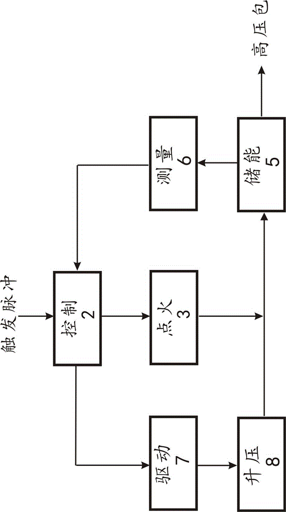
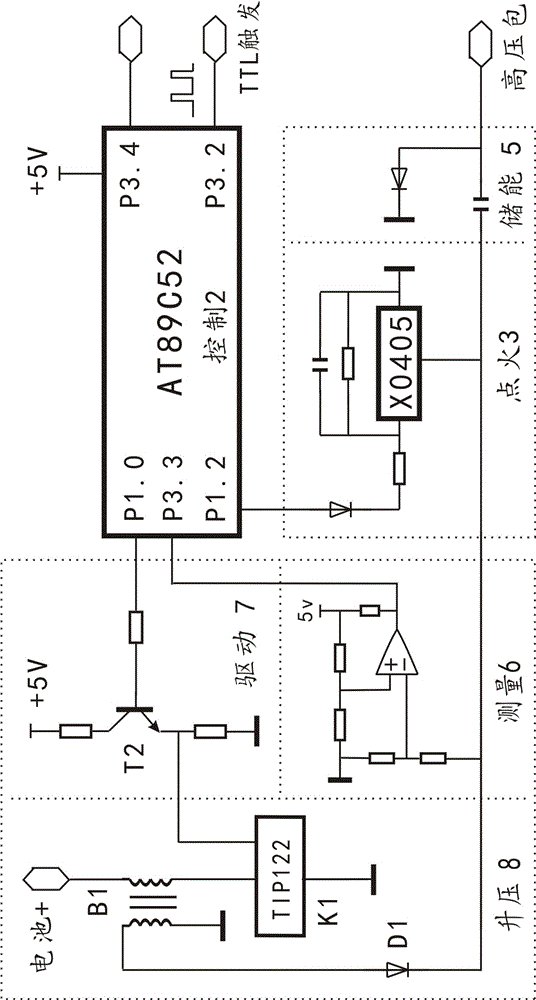
[0055] Example 1: see figure 2 , the duty ratio signal controls the boost motorcycle constant voltage ignition circuit. Including control circuit, ignition circuit, energy storage circuit, drive circuit, boost circuit, measurement circuit. Among them, the ignition circuit, energy storage circuit, and control circuit all adopt standard or common circuits, the relevant circuit diagrams are simplified, and the descriptions are simplified or omitted. The control circuit is a single-chip microcomputer or a collection of single-chip microcomputer and other circuits. The control circuit can also use a digital circuit to imitate a single-chip microcomputer to achieve similar functions without a single-chip microcomputer.

[0056] The control circuit of this example adopts 89C52, and adopts the duty ratio control type boost circuit. P1.0 is connected to the drive circuit. Comprehensively considering the different working conditions of the engine, the voltage required for ignition o...

example 2

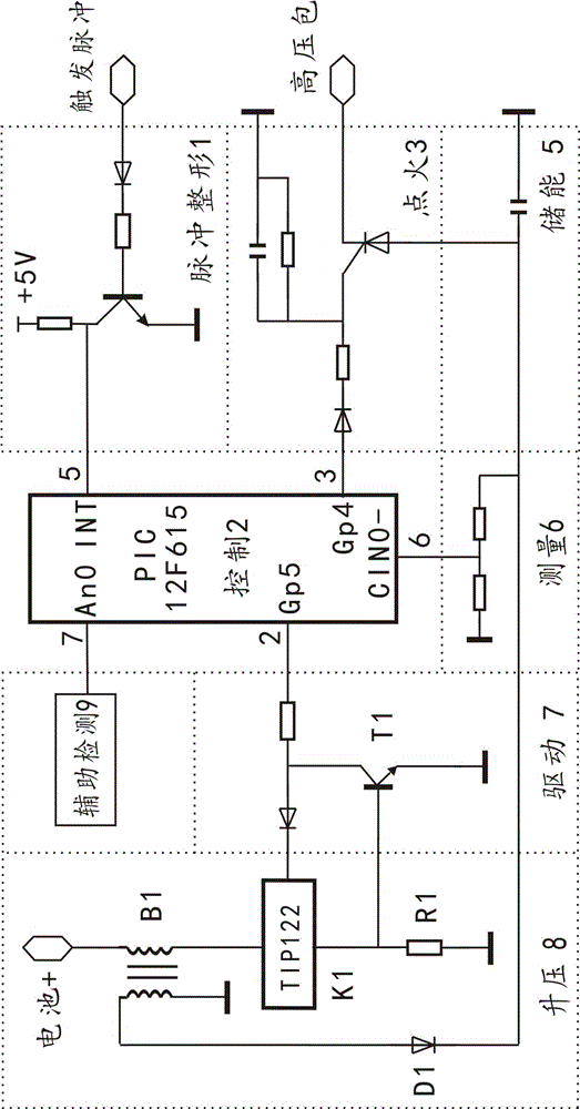
[0068] Example 2: Reference image 3 , with a current-limiting drive duty ratio signal to control the boost constant voltage ignition circuit. Including control circuit, ignition circuit, energy storage circuit, drive circuit, boost circuit, measurement circuit and pulse shaping circuit. The control circuit adopts PIC12F615, and the boost circuit is controlled by a duty ratio signal. The INT end of the microcontroller is connected to the output of the pulse shaping circuit, the GP5 is connected to the input of the drive circuit, and its output is connected to the control end of the boost control end TIP122 of the boost circuit. The driving circuit includes a resistor and a diode, and a primary current limiting circuit of the step-up transformer. The primary current is sampled by R1, and the triode T1 is fed back to the driving side.

[0069] The measurement circuit is a pair of voltage divider resistors, and its voltage divider output is connected to the CIN0- terminal of th...

example 3

[0075] Example 3: Transformer oscillation step-up motorcycle constant voltage and cylinder temperature compensation ignition circuit. refer to Figure 4 , The control circuit is MC9S08JM60 / 32 series. The circuit includes the aforementioned partial circuits and connection principles with corresponding functions. Selected an interrupt input port KBIP7, two output ports PTB4, PTB5, an AD conversion input port ADP2 and an analog comparator input port ACMP-. The single-chip microcomputer is rich in port line resources, and each port can be adjusted according to the needs of peripheral functions. Use other single-chip microcomputer circuits and replace them with port lines with the same function. A transformer oscillating boost circuit is used, and its output is connected to the energy storage circuit through the diode D1.

[0076] The PTB5 of the control circuit sends out a high-level control signal, which reaches the control terminal of the boost circuit through the drive circ...


PUM


Abstract

Gasoline CDI is small in energy scope and cannot accord with the requirements of working conditions of an engine, while battery voltage is seriously affected, and actual defects usually reduce ignition effect and reliability. Because online energy regulation is involved, and concept and technology are complex, acknowledgment for old habits and customs is normal. For online energy regulation, the following principle difficulties need to be solved: the ignition quality is not affected by battery voltage change, especially great reduction of battery voltage; and accurate period-by-period regulation in large scope needs to be carried out according to the requirements of working conditions. The effect and the comprehensive performance are greatly broken through are tend to be perfect. Worthy and matched high-grade ignition technology is provided for an electronic injection engine. Excellent characteristics are based on unprecedented energy storage voltage dynamic measuring and control technology and boosting parameter online regulation technology. Regulation on a complex and changeable energy storage process with energy feedback is controlled by experience and mathematical design accuracy. Mechanical and electrical integration is achieved and stably follows up the requirements of working conditions. Multiple circuits, algorithms and technical methods are deeply created. The created concept is novel and firm and relates to multiple technology and knowledge areas. The application is convenient and reliable.

Description

[0001] This application is a divisional case, the original application name: gasoline engine energy balance ignition circuit and balance control method; original application number: 2012102313054; original application date: 2012-7-5. technical field [0002] The proposal belongs to the technical field of internal combustion engine ignition, and in particular relates to a gasoline engine CDI direct current ignition circuit. Background technique [0003] ] The igniter should fire the engine at the right time and with the right amount of energy. The development of CDI ignition circuit has gone through three generations. The first generation of AC charging plus mechanical control of the advance angle, the second generation of AC or DC charging plus circuit control of the advance angle, and the third generation uses a single-chip microcomputer to make the control of the advance angle more accurate, and it can be accurately controlled. The advance angle is the ignition timing and ...

Claims


Application Information

Patent Timeline
Patent Type & Authority Applications(China)
IPC IPC(8): F02P9/00
CPCF02P9/00F02P9/002
Inventor 曹杨庆
Owner 曹杨庆
Learn More