Energy balance ignition circuit of gasoline engine and balance control method
An ignition circuit and gasoline engine technology, applied in ignition controllers, electric spark ignition controllers, engine ignition, etc., can solve the problem of quantitative control means of energy storage circuit and booster circuit, constant voltage ignition and adjustment of ignition energy according to working conditions Issues such as immature technology
- Summary
- Abstract
- Description
- Claims
- Application Information
AI Technical Summary
Problems solved by technology
Method used
Image
Examples
example 1
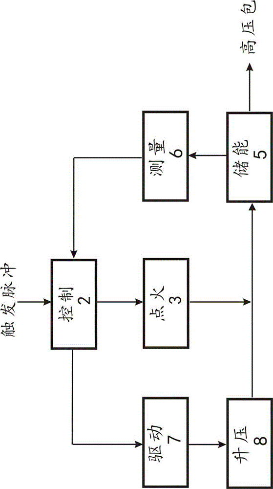
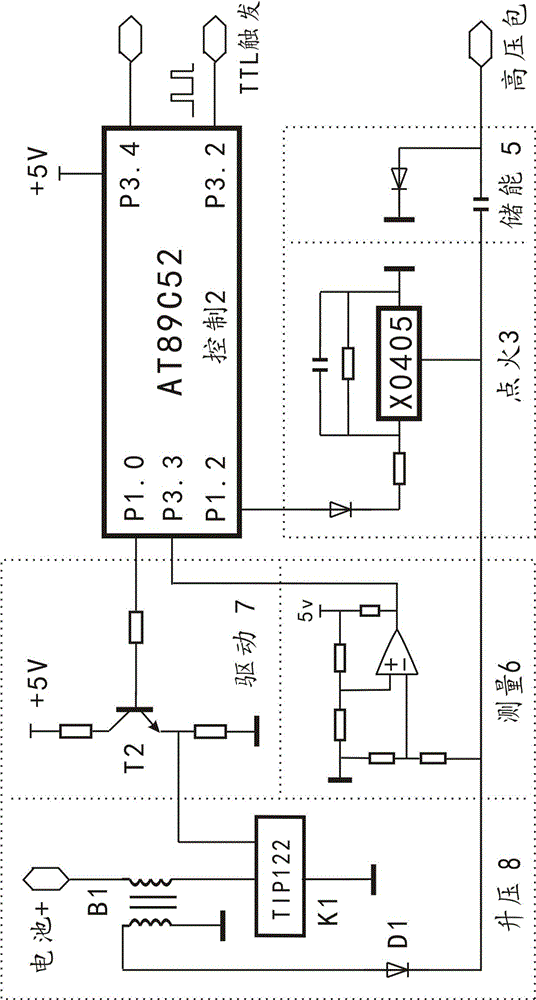
[0054] Example 1: see figure 2 , the duty ratio signal controls the boost motorcycle constant voltage ignition circuit. Including control circuit, ignition circuit, energy storage circuit, drive circuit, boost circuit, measurement circuit. Among them, the ignition circuit, energy storage circuit, and control circuit all adopt standard or common circuits, the relevant circuit diagrams are simplified, and the descriptions are simplified or omitted. The control circuit is a single-chip microcomputer or a collection of single-chip microcomputer and other circuits. The control circuit can also use a digital circuit to imitate a single-chip microcomputer to achieve similar functions without a single-chip microcomputer.
[0055] The control circuit of this example adopts 89C52, and adopts the duty ratio control type boost circuit. P1.0 is connected to the drive circuit. Comprehensively considering the different working conditions of the engine, the voltage required for ignition...
example 2
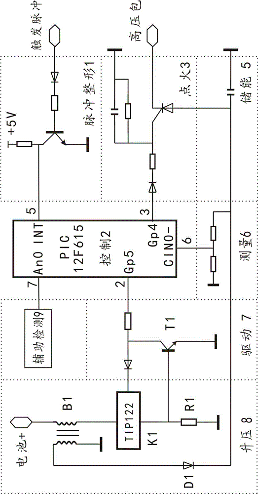
[0067] Example 2: Reference image 3 , with a current-limiting drive duty ratio signal to control the boost constant voltage ignition circuit. Including control circuit, ignition circuit, energy storage circuit, drive circuit, boost circuit, measurement circuit and pulse shaping circuit. The control circuit adopts PIC12F615, and the boost circuit is controlled by a duty ratio signal. The INT end of the microcontroller is connected to the output of the pulse shaping circuit, the GP5 is connected to the input of the drive circuit, and its output is connected to the control end of the boost control end TIP122 of the boost circuit. The driving circuit includes a resistor and a diode, and a primary current limiting circuit of the step-up transformer. The primary current is sampled by R1, and the triode T1 is fed back to the driving side.
[0068] The measurement circuit is a pair of voltage divider resistors, and its voltage divider output is connected to the CIN0- terminal of t...
example 3
[0074] Example 3: Transformer oscillation step-up motorcycle constant voltage and cylinder temperature compensation ignition circuit. refer to Figure 4 , The control circuit is MC9S08JM60 / 32 series. The circuit includes the aforementioned partial circuits and connection principles with corresponding functions. Selected an interrupt input port KBIP7, two output ports PTB4, PTB5, an AD conversion input port ADP2 and an analog comparator input port ACMP-. The single-chip microcomputer is rich in port line resources, and each port can be adjusted according to the needs of peripheral functions. Use other single-chip microcomputer circuits and replace them with port lines with the same function. A transformer oscillating boost circuit is used, and its output is connected to the energy storage circuit through the diode D1.
[0075] The PTB5 of the control circuit sends out a high-level control signal, which reaches the control terminal of the boost circuit through the drive cir...
PUM
 Abstract
Description
Claims
Application Information
 - R&D
- Intellectual Property
- Life Sciences
- Materials
- Tech Scout
- Unparalleled Data Quality
- Higher Quality Content
- 60% Fewer Hallucinations
Browse by: Latest US Patents, China's latest patents, Technical Efficacy Thesaurus, Application Domain, Technology Topic, Popular Technical Reports.
© 2025 PatSnap. All rights reserved.Legal|Privacy policy|Modern Slavery Act Transparency Statement|Sitemap|About US| Contact US: help@patsnap.com


