
Unique solid and safe anti-collision frame

A solid and safe technology, applied to vehicle parts, substructure, transportation and packaging, etc., to achieve the effects of simple and convenient production, superior comprehensive technical performance, and obvious comprehensive economic and environmental benefits in popularization and use

Inactive Publication Date: 2016-06-15
LIUZHOU JINGYANG ENERGY SAVING TECH RES DEV
View PDF6 Cites 0 Cited by
  • Summary
  • Abstract
  • Description
  • Claims
  • Application Information

AI Technical Summary

Problems solved by technology

[0003] The purpose of the present invention is to provide a technical structure with advanced technology structure, excellent performance and wide application, cushioning, safety and anti-collision, high quality, high efficiency and energy saving, safe and reliable, convenient to manufacture, aiming at the lagging technology of the existing automobile head chassis and the development needs of the automobile technology industry market. Unique, strong and safe anti-collision frame with lower cost

Method used


Image

  • Unique solid and safe anti-collision frame

Examples


Embodiment Construction

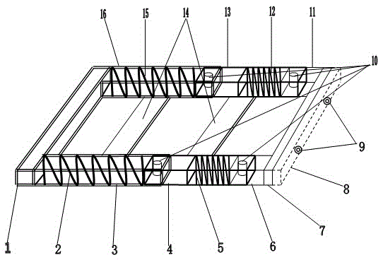
[0013] As shown in the accompanying drawings, the original firm and safe anti-collision vehicle frame of the present invention includes two parts of a main part and an accessory.

[0014] The main parts include a rear bar tube 1, a left rear tube 3, a left middle tube 4, a left front tube 6, a front bar tube 7, a front bumper 8, a right front tube 11, a right middle tube 13, a machine bar 14, and a right rear tube 16,

[0015] The front ends of the rear lever tube 1 are respectively connected to the rear ends of the left rear tube 3 and the right rear tube 16, and its main function is to support the left rear tube 3 and the right rear tube 16,

[0016] The rear end of the left rear pipe 3 is connected to the left end of the rear lever pipe 1 and the front end accommodates the rear end of the left middle pipe 4. Its main function is to support the left middle pipe 4 and the built-in left rear spring 2,

[0017] The rear end of the left middle pipe 4 is placed at the front end ...


PUM


Abstract

The invention relates to an unique solid and safe anti-collision frame, wherein two ends of a rear bumper tube are respectively connected with a left rear tube and a right rear tube; the rear end of the left rear tube is connected with the left end of the rear bumper tube; the rear end of a left middle tube is accommodated within the front end of the left rear tube; the rear end of the left middle tube is placed at the front end of the left rear tube; the rear end of a left front tube is accommodated in the front end of the left middle tube; the rear end of the left front tube is placed on the internal side of the front end of the left middle tube; the front end of the left front tube is connected with the rear side of a front bumper tube; the two ends of the rear side of the front bumper tube are respectively connected with front ends of the left front tube and the right front tube; a front slowing bumper is arranged on the front side of the front bumper tube; the front end of the right front tube is connected with the rear side of the front bumper tube; the rear end of the right front tube is placed in the left middle tube; the rear end of the right front tube is accommodated in the internal side of the front end of the right middle tube; the rear end of the right middle tube is placed in the front end of the right rear tube; machine bumpers are respectively arranged between the left and right rear tubes and between the left and right middle tubes; the rear end of the right middle tube is accommodated in the front end of the right rear tube; the rear end of the right rear tube is connected with the front side of the rear bumper tube; a left rear spring is arranged in the left rear tube; a left front spring is arranged in the left middle tube; inductive heads are arranged at the two ends of the front slowing bumper; inductive bolts are arranged in the left rear tube, the right rear tube, the left middle tube and the right middle tube; the right front spring is arranged in the right middle tube; and the right rear spring is arranged in the right rear tube.

Description

technical field [0001] The invention relates to an anti-collision vehicle frame, in particular to a unique strong and safe anti-collision vehicle frame. Background technique [0002] Nowadays, all kinds of motor vehicle underframes are non-buffering rigid technical structural devices. Although there are many professionals and amateurs in the domestic and foreign auto industry in recent years who continue to study the motor vehicle underframes, various automobiles, especially passenger vehicles There is still no obvious progress in the research and development technology of the motor vehicle head chassis that is configured and used by automobiles, so that the safety consequences of the motor vehicle head in traffic accidents remain the same. For this reason, it is necessary to invent a kind of automobile head collision avoidance device with advanced technical structure, excellent performance and wide adaptability, buffer safety collision avoidance and high-quality, high-effic...

Claims


Application Information

Patent Timeline
Patent Type & Authority Applications(China)
IPC IPC(8): B62D21/15
CPCB62D21/15
Inventor 韦战
Owner LIUZHOU JINGYANG ENERGY SAVING TECH RES DEV
Learn More