
A spiral coil machine

A coiler and spiral technology, applied in the field of mechanical devices, can solve problems such as unsuitable for hot simmering process, difficult to meet process requirements, small ring diameter, etc., achieve high degree of automation, reasonable structure, and reduce the effect of rebound coefficient

Active Publication Date: 2017-10-24
HEBEI INSTALLATION ENG
View PDF6 Cites 0 Cited by
  • Summary
  • Abstract
  • Description
  • Claims
  • Application Information

AI Technical Summary

Problems solved by technology

[0003] Since there are many stainless steel spiral coils in the production of riser heat exchangers, and the ring diameter is small (the diameter of the stainless steel tube is less than 50mm, and the ring diameter of the spiral coil is greater than 200mm), it is not suitable to use the hot simmering process, and manual simmering or The rolling deformation of the plate rolling machine is relatively large, which is not only time-consuming and labor-intensive, but also difficult to meet the process requirements

Method used


Image

  • A spiral coil machine
  • A spiral coil machine
  • A spiral coil machine

Examples


Embodiment Construction

[0025] Below in conjunction with accompanying drawing and embodiment the present invention is described in further detail:

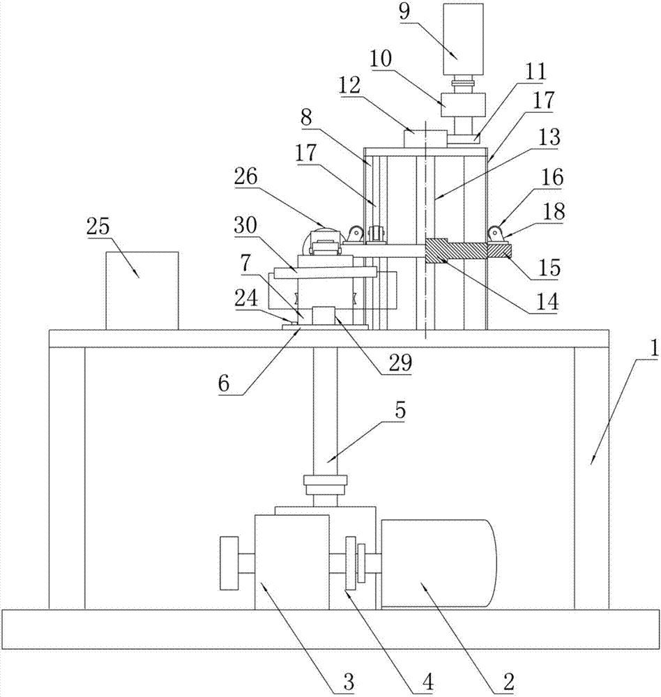
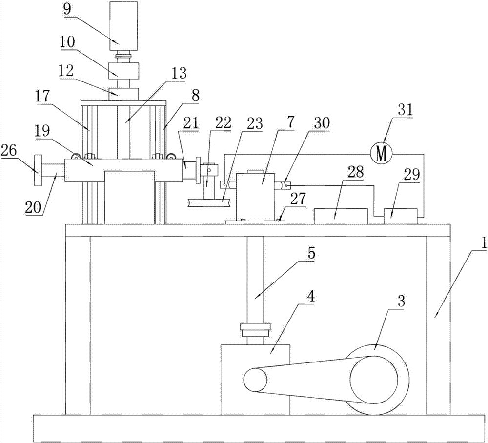
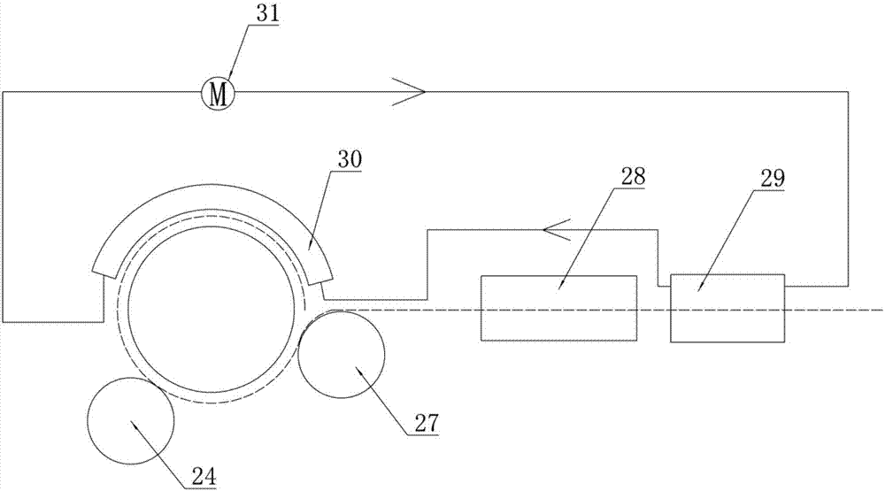
[0026] A spiral coil machine, such as Figure 1 ~ Figure 3 As shown, it includes a frame 1 , a main power system, a coil spacing adjustment system, a coil auxiliary positioning system, an auxiliary anti-rebound system, and an electrical control box 25 installed on the frame 1 .

[0027] The main power system includes a motor 2, a first reducer 3, a second reducer 4, a main shaft 5 and a coil mold. Wherein the motor 2 , the first reducer 3 , the second reducer 4 and the main shaft 5 are located below the frame 1 , and the coil mold is located above the frame 1 . The output shaft of the motor 2 is connected to the first reducer 3 , the output end of the first reducer 3 is connected to the second reducer 4 , and the output end of the second reducer 4 is connected to the vertically arranged main shaft 5 . The output speed of the motor 2 is 1400r / min~1500r / ...


PUM


Abstract

A spiral coil machine comprises a rack, a main power system, a coil distance adjustment system and a coil auxiliary positioning system. The main power system comprises a motor which is connected with a vertical main axle by two-level speed reduction, the coil positioner is coaxially connected with the upper end of the main axle and extends outside the upper surface of the rack; the coil distance adjustment system comprises a bracket fixed on the rack, a driving gear which is connected with a speed regulation motor is arranged above the bracket and engaged with and drives a driven gear, the driven gear is coaxially connected with a first vertical screw, the first screw is connected with a frame by an axle sleeve, the frame is arranged on the outer side of the bracket and provided with pulleys. The coil auxiliary positioning system comprises a support frame which is fixed on one side of the frame corresponding with the coil positioner, a second horizontal screw is mounted on the support frame and cooperatively provided with a slider, and a top wheel is mounted on one end of the slider corresponding with the coil positioner by a vertical axle. During the pipeline heating process, the automatic degree is high, the size is accurate, one person can produce the coil at high efficiency, and labor and power are saved.

Description

technical field [0001] The invention relates to a mechanical device, in particular to a spiral coil machine for making small-diameter spiral coils in ascending heat exchange tubes. Background technique [0002] At present, the rising pipe of coke oven raw gas in the coking industry is transformed and replaced with a rising pipe heat exchanger with a spiral coil device, which absorbs the heat of raw gas to generate saturated steam, which is energy-saving and environmentally friendly, and has a good market prospect. [0003] Since there are many stainless steel spiral coils in the production of riser heat exchangers, and the ring diameter is small (the diameter of the stainless steel tube is less than 50mm, and the ring diameter of the spiral coil is greater than 200mm), it is not suitable to use the hot simmering process, and manual simmering or The rolling deformation of the plate rolling machine is relatively large, which is not only time-consuming and labor-intensive, but ...

Claims


Application Information

Patent Timeline
Patent Type & Authority Patents(China)
IPC IPC(8): B21D11/06B21D37/16
CPCB21D11/06B21D37/16
Inventor 赵海生张福成李献国彭昭加张卫元
Owner HEBEI INSTALLATION ENG
Learn More