
Optical fiber recoating device

A covering device and optical fiber technology, applied to the surface coating liquid device, optics, light guide, etc., can solve the problems of wasting resin, covering, resin bubbles, etc., and achieve effective and flexible effects

Active Publication Date: 2016-06-08
THE FUJIKURA CABLE WORKS LTD
View PDF7 Cites 5 Cited by
  • Summary
  • Abstract
  • Description
  • Claims
  • Application Information

AI Technical Summary

Problems solved by technology

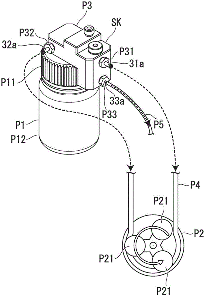
[0005] However, in the prior art described above, for example, in the case of using a tube pump in which resin is supplied to the optical fiber covering part (corresponding to the above-mentioned mold part) by pressing the tube with a plurality of rollers, air bubbles are generated in the resin due to negative pressure.
Therefore, in the above-mentioned prior art, there is a problem that the optical fiber is covered with the resin mixed with air bubbles.
In addition, for example, it is also considered to remove the air bubbles from the resin by discarding the resin containing the air bubbles, but there is a problem of wasting the resin due to the disposal.

Method used


Image

  • Optical fiber recoating device
  • Optical fiber recoating device
  • Optical fiber recoating device

Examples


Embodiment Construction

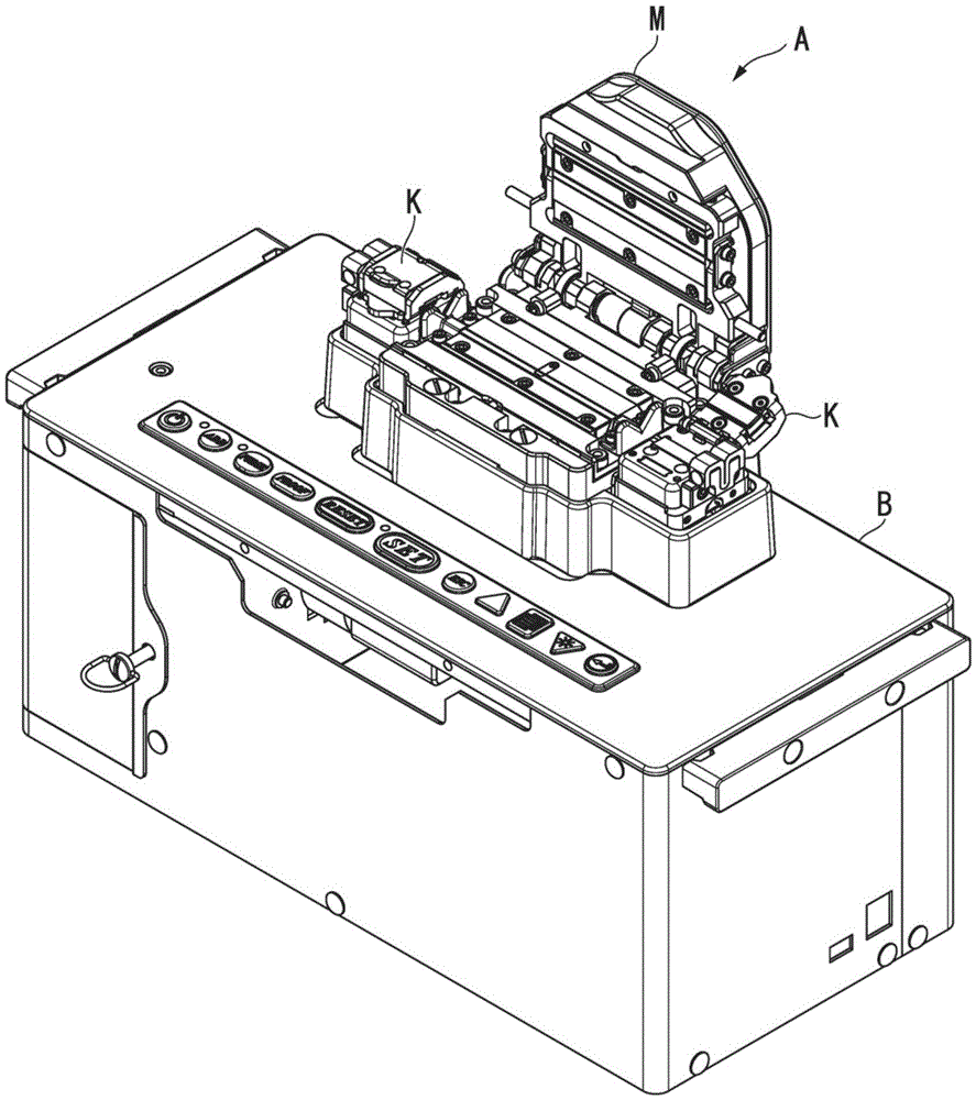
[0021] The optical fiber recoating device A of the present embodiment is a device for recoating the portion after the optical fiber-type optical component is manufactured by removing the coating (intermediate coating) of an arbitrary intermediate portion of the optical fiber. In addition, in the optical fiber recovered by the above-mentioned optical fiber recovering device A, the covering part and the cover covering the outer peripheral side of the covering part are formed concentrically from the axis. In addition, the covering of the optical fiber is made of, for example, an ultraviolet curable resin such as urethane acrylate, epoxy acrylate, polybutadiene acrylate, silicone acrylate, polyester acrylate, or the like.

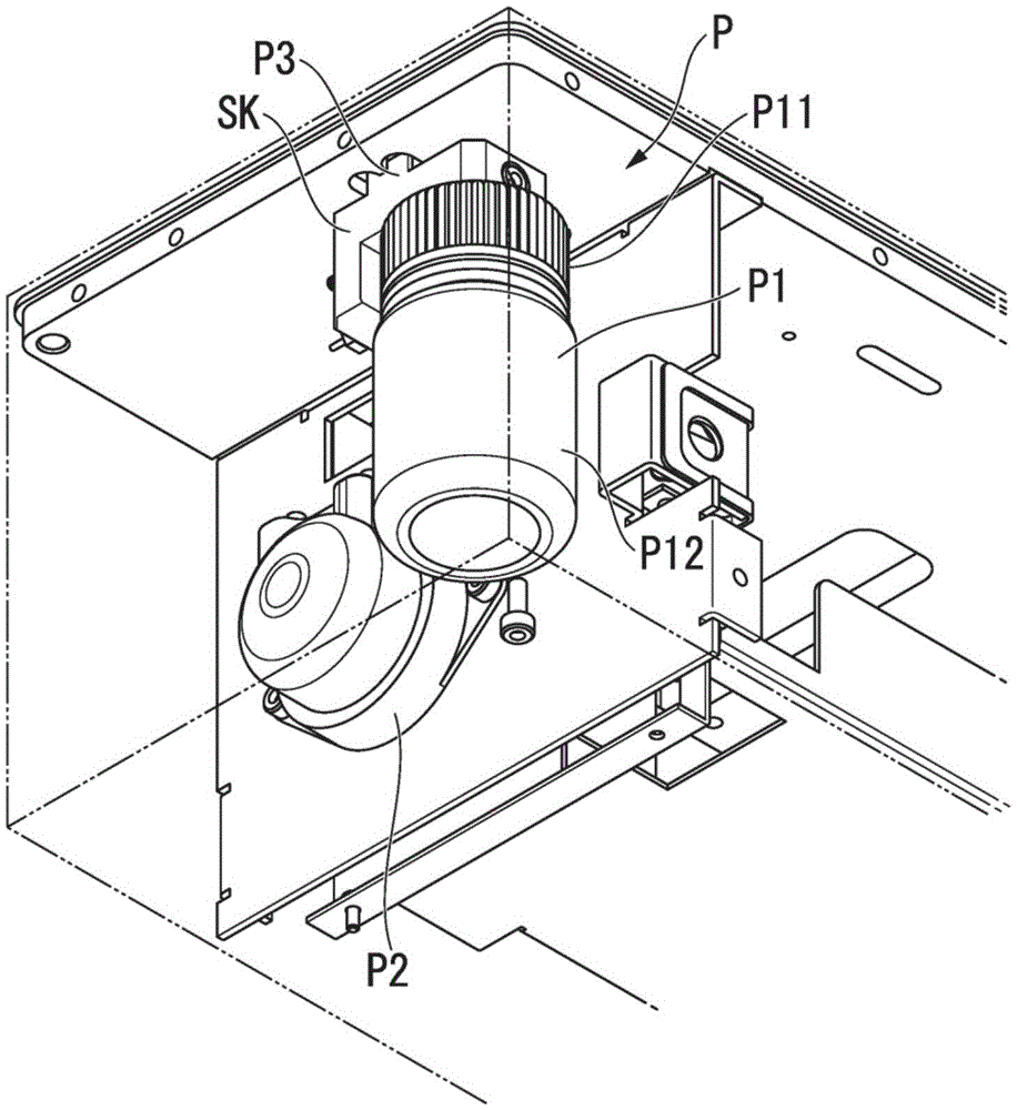
[0022] Such as figure 1 as well as figure 2 As shown, the above-mentioned optical fiber recoating device A includes an optical fiber covering part M, an optical fiber holding part K, a base B, and a resin supply part P.

[0023] Such as figure 1 As shown, t...


PUM


Abstract

This optical fiber recoating device is provided with an optical fiber coating unit (M) for curing resin and coating a coating-removed portion of an optical fiber with the cured resin. The optical fiber recoating device is provided with a resin storage tank (P1) for storing the resin that has not been cured, a pump (P2) for supplying the resin stored in the resin storage tank (P1) to the optical fiber coating unit (M), and a bubble separator (P3) for separating bubbles included in the resin from the pump (P2), pumping the resin from which the bubbles have been separated to the optical fiber coating unit (M), and returning the resin in which the separated bubbles are included to the resin storage tank (P1).

Description

technical field [0001] The present invention relates to an optical fiber recovering device. [0002] this application claims priority based on Japanese Patent Application No. 2014-202263 for which it applied to Japan on September 30, 2014, and uses the content here. Background technique [0003] Patent Document 1 below discloses a molding die for covering an optical fiber in which a first die groove is utilized by combining a first base formed with a first die groove and a second base formed with a second die groove. The mold part is constituted with the second mold groove. In the molding mold, a first position adjustment groove for fitting a position adjustment member is formed on the surface of the first base on which the first mold groove is formed. The surface of the seat on which the second mold groove is formed is formed with a second position adjustment groove for fitting the position adjustment member, and at least one of the first base or the second base is formed ...

Claims


Application Information

Patent Timeline
Patent Type & Authority Applications(China)
IPC IPC(8): G02B6/44B29C39/10C03C25/12
CPCC03C25/12B05C11/1039B05C11/11B05C11/10B05C3/12G02B6/02033
Inventor 神田佳治横田耕一吉田裕树
Owner THE FUJIKURA CABLE WORKS LTD
Learn More