
Hanging bracket special for movement of steel rail and application method of hanging bracket

A technology of rails and hangers, applied in the field of engineering technology and science, can solve the problems of bulkiness, inconvenient transition, and limited application scope, and achieve the effect of ensuring safety and avoiding contamination.

Active Publication Date: 2016-06-08
CHINA RAILWAY SHANGHAI ENGINEERING BUREAU GROUP CO LTD +1
View PDF11 Cites 13 Cited by
  • Summary
  • Abstract
  • Description
  • Claims
  • Application Information

AI Technical Summary

Problems solved by technology

However, most of the special hangers are complex in structure and relatively heavy, and it is becoming more and more difficult to meet various working conditions and construction operations in complex environments.
In terms of structural connection, the beam and the outriggers are usually fixed by welding. When there are steps in the construction site, the heights of the outriggers on both sides are different, making it difficult to use
And because it is not detachable, it brings a lot of inconvenience to the transition
The running part generally uses the pin shaft to pass through the wheel, and then welded to the leg through the lug plate. The steel wheel is in direct contact with the pin shaft, and the friction force is large when rotating, which makes it inconvenient to push and the scope of application is more limited.

Method used


Image

  • Hanging bracket special for movement of steel rail and application method of hanging bracket
  • Hanging bracket special for movement of steel rail and application method of hanging bracket
  • Hanging bracket special for movement of steel rail and application method of hanging bracket

Examples


Embodiment Construction

[0036] The present invention will be further described below in conjunction with accompanying drawing, and the structure and principle of this device are very clear to those skilled in the art. It should be understood that the specific embodiments described here are only used to explain the present invention, not to limit the present invention.

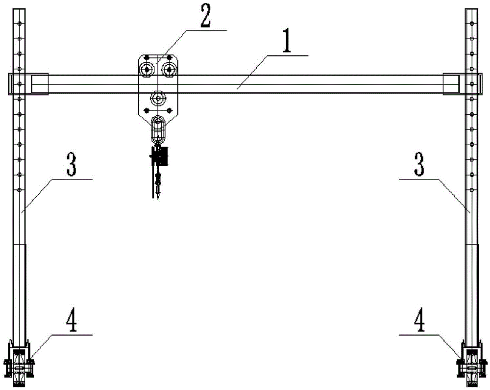
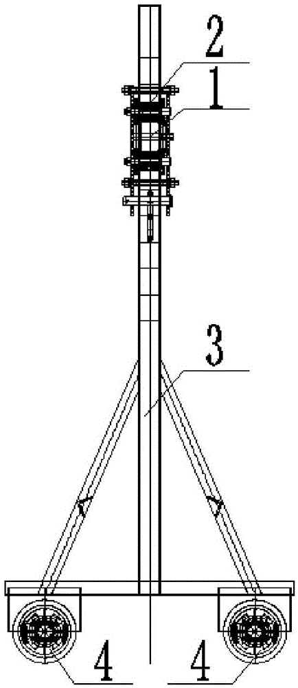
[0037] In order to achieve the above object, the design of the present invention is mainly composed of four parts, which are respectively: crossbeam, suspension rail trolley, supporting legs, running mechanism, such as Figure 1(a) ~ Figure 1(b) shown. The beam is composed of a rectangular steel pipe and a guide sleeve. Both ends of the rectangular steel pipe are welded with the guide sleeve. The rectangular steel pipe adopts 120mm×80mm×6mm cold-drawn seamless steel pipe. The top and bottom of the guide sleeve are designed with round holes matching the size of the outrigger column, and the middle part is designed with a Φ22 round h...


PUM

PropertyMeasurementUnit
Diameteraaaaaaaaaa

Abstract

The invention relates to the engineering technology science, in particular to a design and application method of a hanging bracket special for movement of a steel rail in urban railway field operation. The hanging bracket special for movement of the steel rail comprises a chain block, a cross beam, a hanger rail trolley, landing leg stand columns and walking mechanisms, and is characterized in that the cross beam is arranged between the two landing leg stand columns and provided with the hanger rail trolley, and the bottoms of the two landing leg stand columns are each provided with one corresponding walking mechanism. The cross beam and landing legs are connected through guide sleeves, the supporting height of the parts, on the landing legs on the two sides, of the cross beam can be adjusted according to field conditions, and the construction need under the condition that a construction site is bumpy severely or steps exist can be met. A sealed wheel set assembly of conical roller bearings is adopted in design of the walking mechanisms, and therefore pushing at the construction field is facilitated, contamination can be avoided, and the hanging bracket can adapt to the severe construction environment. Three sets of rollers arranged in an inverted triangle manner are adopted in the hanger rail trolley so that the hanger rail trolley cannot fall off when moving on the cross beam, and safety can be guaranteed.

Description

[technical field] [0001] The invention relates to engineering technology science, and relates to the design and use method of a special hanger for rail movement in urban rail on-site operations. [Background technique] [0002] At present, in my country's urban rail construction, special hangers have been generally used for the movement and hoisting of small-scale rails on the ground line site. However, most of the special hangers are complex in structure and relatively cumbersome, which has become more and more difficult to meet various working conditions and construction operations in complex environments. In terms of structural connection, the beam and the outriggers are usually fixed by welding. When there are steps in the construction site, the heights of the outriggers on both sides are different, making it difficult to use. And because it is not detachable, it brings a lot of inconvenience to the transition. The running part generally uses the pin shaft to pass throu...

Claims


Application Information

Patent Timeline
IPC IPC(8): B66C19/00B66C9/00B66C5/02
CPCB66C5/02B66C9/00B66C19/00
Inventor 白向臣刘习生胡漳敏汪晓俊刘存牛刘绩陈金龙陈付平
Owner CHINA RAILWAY SHANGHAI ENGINEERING BUREAU GROUP CO LTD
Learn More