DC power supply units, motor drive units, air conditioners and refrigerators
A technology of DC power supply and driving device, which can be used in motor control, emergency protection circuit devices, high-efficiency power electronic conversion, etc., and can solve problems such as short-circuit damage
- Summary
- Abstract
- Description
- Claims
- Application Information
AI Technical Summary
Problems solved by technology
Method used
Image
Examples
Embodiment approach 1
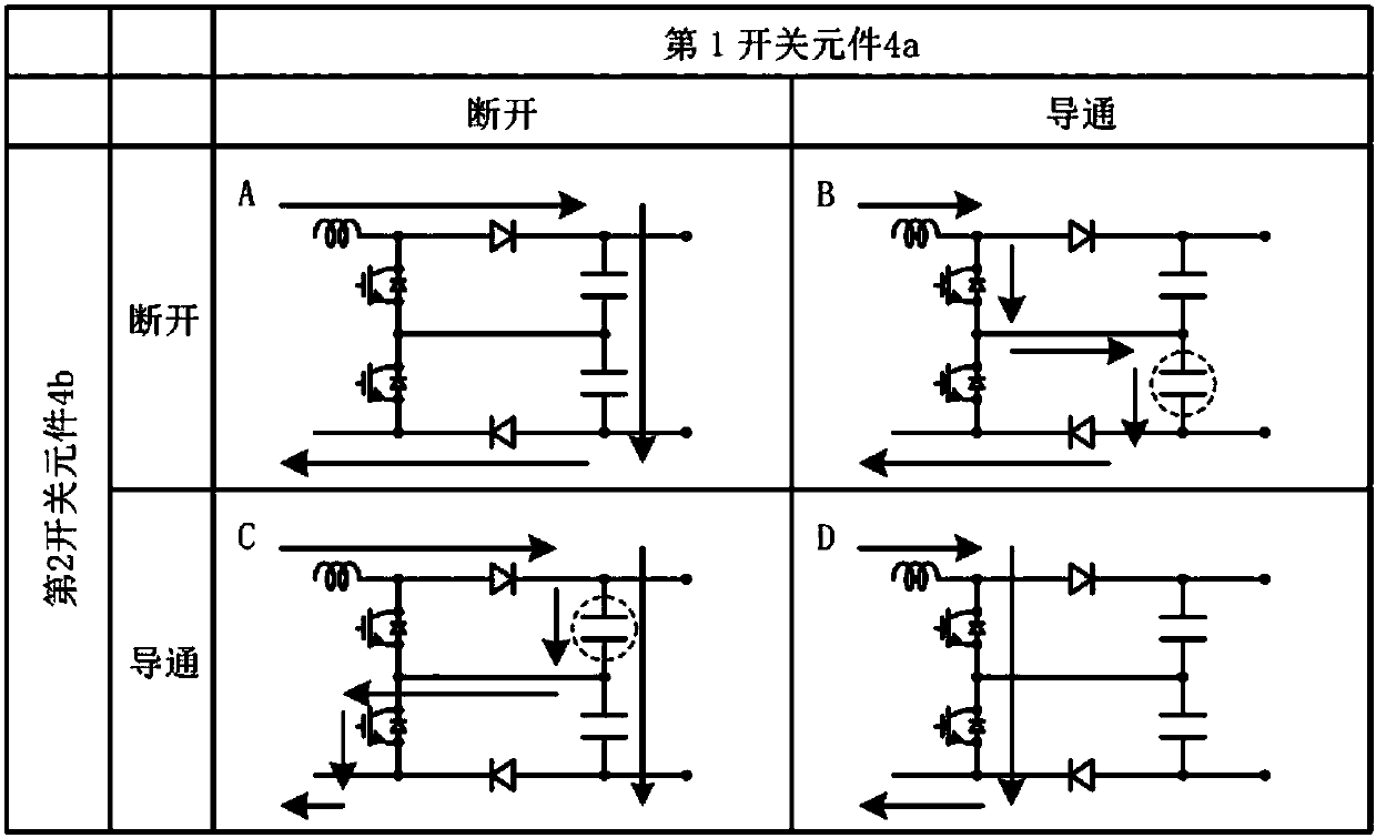
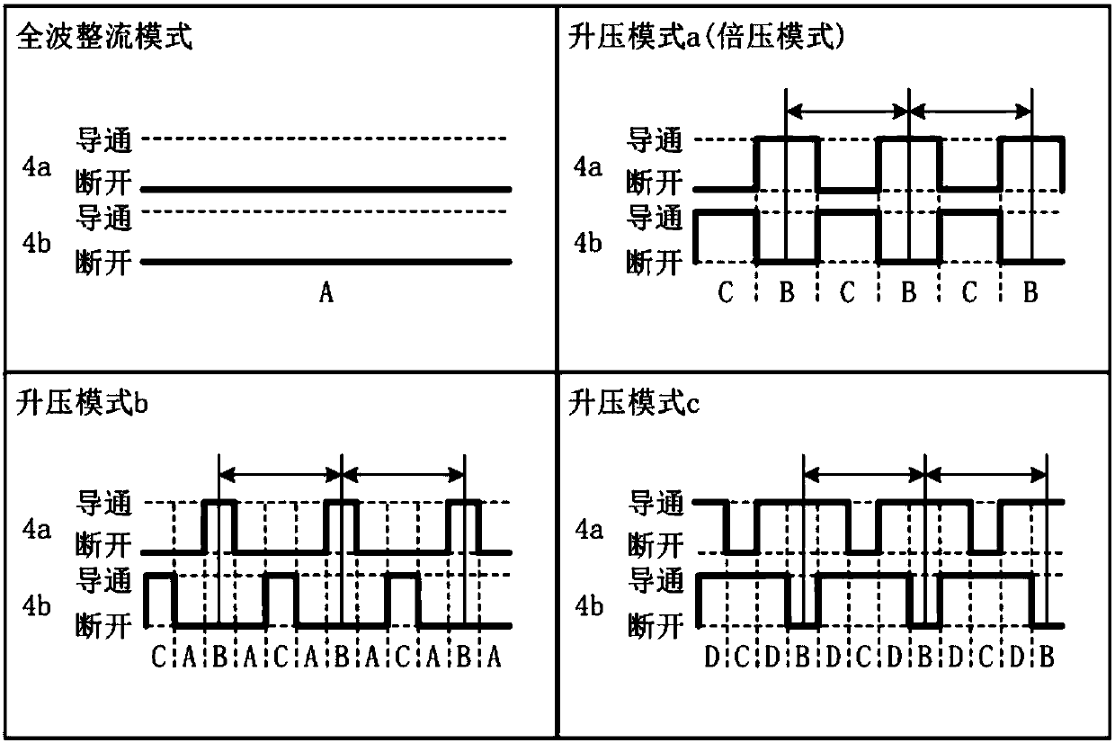
[0054] figure 1 It is a circuit block diagram showing a configuration example of the first embodiment of the DC power supply device 100 according to the present invention. The DC power supply device 100 of this embodiment is a power conversion device that converts AC to DC, and converts the three-phase AC supplied from the AC power supply 1 into DC to supply to the load 11 . The load 11 may be any load that consumes power in direct current. Here, the load 11 is assumed to be an inverter load that drives a motor of a compressor used in equipment to which a refrigeration cycle is applied, for example. Examples of equipment to which a refrigeration cycle is applied include air conditioners, refrigerators, washing and drying machines, refrigerators, dehumidifiers, heat pump water heaters, and showcases. The load 11 is not limited to the load of equipment using a refrigeration cycle, and may also be a load of a vacuum cleaner, a fan motor or an exhaust fan, a hand dryer, inductio...
Embodiment approach 2
[0093] Figure 7 It is a circuit block diagram showing a configuration example of a motor drive device according to Embodiment 2 of the present invention. exist Figure 7 In, pair with figure 1 Components that operate in the same manner as those shown in the circuit configuration are denoted by the same reference numerals as in Embodiment 1, and redundant descriptions are omitted. Figure 7 The shown motor drive device includes the DC power supply device 100 according to the first embodiment. figure 1 A load of 11 with Figure 7 The inverter 30 corresponds to the motor 31. The inverter 30 is connected to both ends of a series circuit composed of the first capacitor 6a and the second capacitor 6b. A DC voltage is input to the inverter 30 .
[0094] The motor drive device of the present embodiment includes a current detector 32 and a drive control unit 33 in addition to the DC power supply device 100 of the first embodiment. The current detector 32 (32a, 32b) detects the ...
Embodiment approach 3
[0105] Figure 8It is a circuit block diagram showing a configuration example of an air conditioner according to Embodiment 3 of the present invention. The air conditioner of this embodiment has the motor drive device demonstrated in Embodiment 2. FIG. The air conditioner of the present embodiment has a compressor 41 incorporating the motor 31 of Embodiment 2, a four-way valve 42 , an outdoor heat exchanger 43 , an expansion valve 44 , and an indoor heat exchanger 45 assembled through refrigerant piping 46 . The refrigeration cycle constitutes a split air conditioner.
[0106] A compression mechanism 47 for compressing the refrigerant and an electric motor 31 for operating it are arranged inside the compressor 41, and the refrigerant is circulated from the compressor 41 to between the heat exchangers 43 and 45 to perform cooling, heating, etc. refrigeration cycle. Figure 8 The shown circuit block can be applied not only to an air conditioner but also to equipment having a ...
PUM
 Abstract
Description
Claims
Application Information
 - R&D
- Intellectual Property
- Life Sciences
- Materials
- Tech Scout
- Unparalleled Data Quality
- Higher Quality Content
- 60% Fewer Hallucinations
Browse by: Latest US Patents, China's latest patents, Technical Efficacy Thesaurus, Application Domain, Technology Topic, Popular Technical Reports.
© 2025 PatSnap. All rights reserved.Legal|Privacy policy|Modern Slavery Act Transparency Statement|Sitemap|About US| Contact US: help@patsnap.com


