Electric motor diagnosing device
A diagnostic device and motor technology, applied in the direction of motor generator testing, measuring devices, measuring electricity, etc., can solve the problems of unrealistic application, large number of wiring, etc., and achieve the effect of high-precision short-circuit faults
- Summary
- Abstract
- Description
- Claims
- Application Information
AI Technical Summary
Problems solved by technology
Method used
Image

Examples
Embodiment approach 1
[0027] Below, refer to Figure 1 to Figure 5 The motor diagnosis device according to Embodiment 1 will be described.
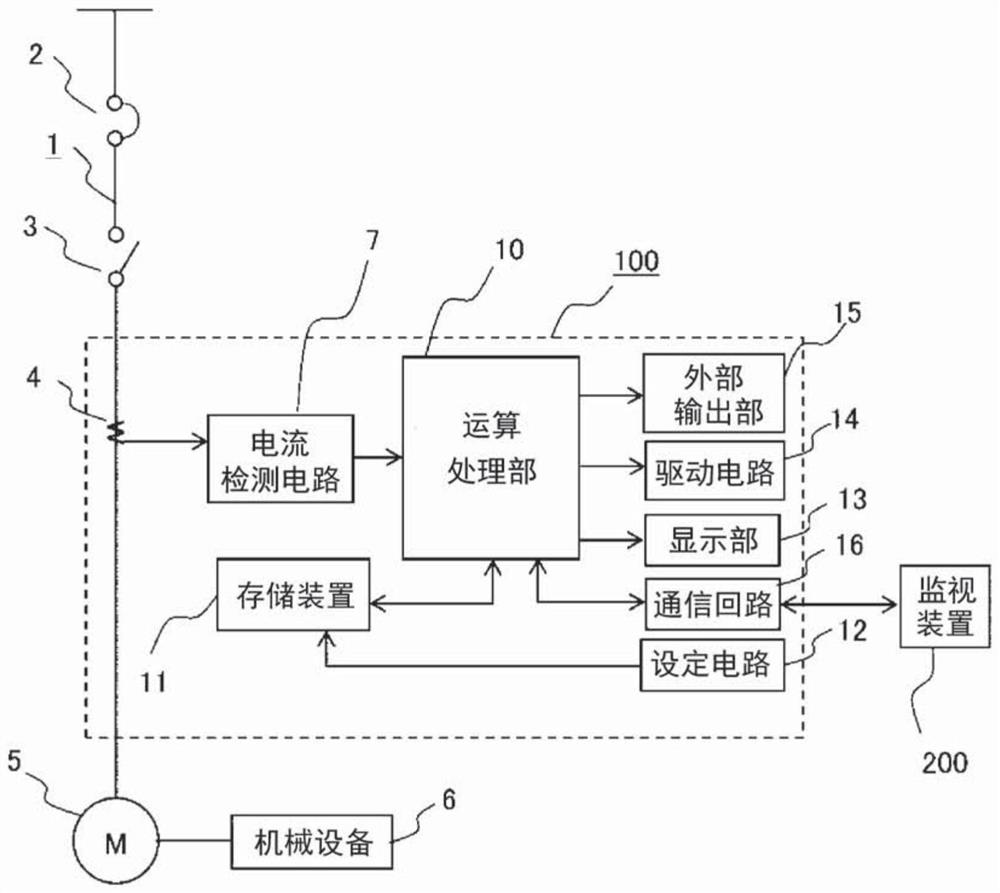
[0028] figure 1 It is a circuit configuration diagram showing the motor diagnosis device according to Embodiment 1, and is mainly used as a control center of an enclosed switchboard. In the figure, a circuit breaker 2 for wiring, an electromagnetic contactor 3 , an instrument converter 4 for detecting a load current of the main circuit 1 , etc. are provided in a main circuit 1 of a power source introduced from a power system. In addition, a motor 5 is connected as a load, and the mechanical device 6 is driven by the motor 5 .
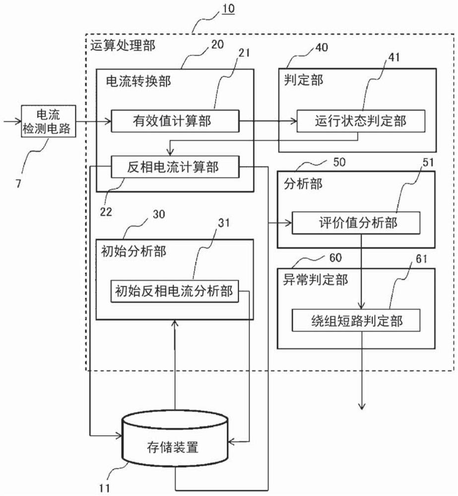
[0029] The motor diagnosis device 100 includes a current detection circuit 7 connected to the meter inverter 4, an arithmetic processing unit 10, a storage device 11, a setting circuit 12, a display unit 13, a drive circuit 14, an external output unit 15, and a communication circuit 16. .
[0030] The current detection circuit 7 con...
Embodiment approach 2
[0081] Below, refer to Figure 6 to Figure 9 A diagnostic device for a motor according to Embodiment 2 will be described.
[0082] Figure 6 It is a circuit configuration diagram showing a diagnostic device for a motor according to Embodiment 2. It is different from Embodiment 1 in that an instrument transformer 8 for detecting the voltage of the main circuit 1 is provided in the main circuit 1 , and an instrument transformer 8 is provided in the motor. The diagnostic device 100 is provided with a voltage detection circuit 9 connected to a meter transformer 8 . Other configurations are the same as those of Embodiment 1.
[0083] The voltage detection circuit 9 detects the line-to-line voltage of the main circuit 1 of the power supply connected to the motor, converts it into a predetermined signal such as the phase voltage of the motor 5 to detect the voltage of the motor, and outputs it to the arithmetic processing unit 10 and the storage device 11 .
[0084] The arithmeti...
Embodiment approach 3
[0112] In Embodiments 1 and 2, the calculation is repeated multiple times (predetermined number of times) and averaged to obtain the initial reverse-phase current value Isn0 before making the winding short-circuit determination. Type and each specification to generate a corresponding table of voltage unbalance rate and reverse current, so as to keep the initial reverse current value Isn0.
[0113] Figure 10 It is a figure which shows the correspondence relationship between the voltage unbalance rate and the reverse current in a tabular form. First, the method of creating this table will be described. Prepare a row for the sequence Vun(n) and a row for the voltage unbalance rate Vunbal. If the preset threshold δ2 for the voltage unbalance rate Vunbal is set to 1%, then the sequence Vun(0), Vun(1), Vun(2), ..., Vun(7), The voltage unbalance rate Vunbal (%) corresponding to Vun(8) and Vun(9) is 0≤Vunbal≤0.1, 0.1<Vunbal≤0.2, 0.2<Vunbal≤0.3, ..., 0.7<Vunbal≤0.8 , 0.8<Vunbal≤0....
PUM
 Abstract
Description
Claims
Application Information
 - R&D
- Intellectual Property
- Life Sciences
- Materials
- Tech Scout
- Unparalleled Data Quality
- Higher Quality Content
- 60% Fewer Hallucinations
Browse by: Latest US Patents, China's latest patents, Technical Efficacy Thesaurus, Application Domain, Technology Topic, Popular Technical Reports.
© 2025 PatSnap. All rights reserved.Legal|Privacy policy|Modern Slavery Act Transparency Statement|Sitemap|About US| Contact US: help@patsnap.com