A permanent magnet single-phase switched reluctance motor and its control method

A switched reluctance motor, permanent magnet technology, applied in electromechanical devices, electrical components, electronic commutators, etc., can solve the problems of unable to generate continuous torque output, reduce motor power factor, unable to achieve bidirectional operation, etc. Achieve the effect of eliminating torque ripple, improving conversion efficiency, and good energy-saving effect

Active Publication Date: 2018-10-09
上海鼎特电器有限公司 +1
View PDF6 Cites 0 Cited by
  • Summary
  • Abstract
  • Description
  • Claims
  • Application Information

AI Technical Summary

Problems solved by technology

However, after the salient pole of the rotor is deformed, it is no longer the double salient pole structure in the original sense, so it will also lose or weaken the unique characteristics of the traditional double salient pole switched reluctance motor, and its control characteristics will also change, and this This kind of motor cannot realize bidirectional operation; in addition, the traditional single-phase switched reluctance motor has the disadvantages of large output torque fluctuation, low output torque density, and inability to produce continuous torque output.
[0004] In addition, if figure 1 As shown, in the control system of the traditional single-phase switched reluctance motor, the original energy in the stator winding needs to be released when the motor commutates. Or feed back the power supply by means of forced commutation, but at this time, the remaining energy of this part not only cannot do useful work, but also forms a reactive current, which will not only reduce the power factor of the motor, but may even affect the operation of the motor

Method used


Image

  • A permanent magnet single-phase switched reluctance motor and its control method
  • A permanent magnet single-phase switched reluctance motor and its control method
  • A permanent magnet single-phase switched reluctance motor and its control method

Examples


Embodiment 1

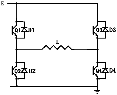
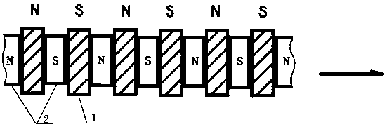
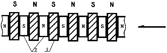
[0047] Embodiment 1: as figure 2 and 3 As shown, a permanent magnet single-phase switched reluctance motor includes a motor output shaft, a control system and at least one set of armature devices. In this embodiment, the armature devices are one group, and the armature devices It includes a stator 1 and a rotor 2. There is an air gap between the salient poles of the stator 1 and the rotor 2. The rotor 2 is fixedly sleeved on the outer periphery of the motor output shaft 5. The number of salient poles on the stator 1 is the same as that on the rotor 2. The number of salient poles is the same, the stator electromagnetic winding 4 is installed at the salient pole part of the stator 1, and the winding directions of the adjacent stator electromagnetic windings 4 are different, that is, the stator electromagnetic windings installed at the salient pole part of the stator They can be connected in series, in parallel, or combined in series and parallel. The head of the first stator e...

Embodiment 2

[0051] Embodiment 2: as Figure 4 , 5 As shown in and 6, in this embodiment, the armature devices are two groups, that is, the stator 1 of the permanent magnet type single-phase switched reluctance motor is composed of a front stator core and a rear stator core, and the The rotor 2 is composed of a front rotor core and a rear rotor core. The stators and rotor cores included in the front and rear segments respectively form independent and self-closing magnetic field circuits.

[0052] Wherein, the number of salient poles of the front stator core and the rear stator core is equal, and there is a gap between the two stator cores, and the salient pole positions in the front stator core and the rear stator core are as follows: Cross positioning arrangement, that is, the salient pole centerline of the front stator core corresponds to the concave center line of the rear stator core, and the stator electromagnetic winding on the front stator core is the same as the stator electromagn...

Embodiment 3

[0056] Embodiment 3: as Figure 7 and 8 As shown, in this embodiment, the armature devices are two groups, that is, the stator 1 of the permanent magnet single-phase switched reluctance motor is composed of a front stator core and a rear stator core, and the rotor 2 It is composed of the front rotor core and the rear rotor core. The stator and rotor core contained in the front and rear segments respectively form an independent and self-closing magnetic field circuit.

[0057] Wherein, the number of salient poles of the front stator core and the rear stator core is equal, and there is a gap between the two stator cores, and the salient pole positions in the front stator core and the rear stator core are as follows: Cross positioning arrangement, that is, the salient pole centerline of the front stator core corresponds to the concave center line of the rear stator core, and the stator electromagnetic winding on the front stator core is the same as the stator electromagnetic win...


PUM


Abstract

The invention discloses a permanent magnetism type single-phase switched reluctance motor. The permanent magnetism type single-phase switched reluctance motor comprise a motor output shaft, a control system and at least one set of armature device; the armature device comprises a stator and a rotor; air gaps are located between the salient poles of the stator and the rotor; the rotor fixedly sleeves the outer periphery of a motor output shaft; the number of the salient poles on the stator is consistent with the number of the salient poles on the rotor; stator electromagnetic windings are installed at the salient poles of the stator; the winding directions of adjacent stator electromagnetic windings are different; permanent magnets are embedded in the salient poles of the rotor; the magnetizing direction of the permanent magnets is radial; and the polarities of the permanent magnets embedded in adjacent salient poles of the rotor are different. The permanent magnetism type single-phase switched reluctance motor of the invention has the advantages of a conventional switched reluctance motor, and can eliminate the torque ripples of the conventional switched reluctance motor, realize bidirectional operation and improve the conversion efficiency of power source input energy. The power density of the motor can be improved. With the motor of the invention adopted, the purpose of energy conservation can be realized effectively.

Description

technical field [0001] The invention belongs to the field of motors, in particular to a permanent magnet type single-phase switched reluctance motor with reusable input energy and a control method thereof. Background technique [0002] The stator and rotor of the traditional two-phase switched reluctance motor are both salient pole structures, and the stator and rotor cores have the same number of teeth. The stator and rotor cores are single-segment cores. The pole interaction generates torque, so its structure is simple and its operation is reliable. [0003] In a conventional single-phase switched reluctance motor, due to consideration of the starting problem of the motor, it is generally necessary to deform the salient poles of the rotor of the motor so that the motor can achieve the purpose of self-starting. However, after the salient pole of the rotor is deformed, it is no longer the double salient pole structure in the original sense, so it will also lose or weaken th...

Claims


Application Information

Patent Timeline
Patent Type & Authority Patents(China)
IPC IPC(8): H02K29/03H02M7/797H02P6/16
CPCH02K29/03H02M7/797H02P6/16
Inventor 陈奚平
Owner 上海鼎特电器有限公司
Why Eureka
Try Eureka