
Outdoor unit refrigerant pipeline system, air conditioner and refrigeration control method for air conditioner

A technology of refrigerant pipeline and outdoor unit, which is applied in refrigerators, refrigeration components, refrigeration and liquefaction, etc., can solve the problem that the output of the compressor drops to a very low level, it is not enough to increase the condensing pressure of the system, and the superheat degree of the exhaust and return air of the compressor is insufficient. and other problems to achieve the effect of ensuring stability and increasing condensing pressure

Active Publication Date: 2016-06-01
GD MIDEA HEATING & VENTILATING EQUIP CO LTD +1
View PDF9 Cites 9 Cited by
  • Summary
  • Abstract
  • Description
  • Claims
  • Application Information

AI Technical Summary

Problems solved by technology

However, in large-capacity systems, due to the large displacement of the compressor and the limitation of the minimum operating frequency of the compressor, it is impossible to reduce the output of the compressor to a very low level; in addition, some systems can reduce heat transfer by closing part of the condenser area, but it is not enough to increase the condensing pressure of the system under extreme conditions, and the problem of insufficient superheat of the exhaust and return air of the compressor will still occur, which will affect the reliability and comfort of the system

Method used


Image

  • Outdoor unit refrigerant pipeline system, air conditioner and refrigeration control method for air conditioner
  • Outdoor unit refrigerant pipeline system, air conditioner and refrigeration control method for air conditioner
  • Outdoor unit refrigerant pipeline system, air conditioner and refrigeration control method for air conditioner

Examples


Embodiment Construction

[0048] The following will clearly and completely describe the technical solutions in the embodiments of the present invention with reference to the accompanying drawings in the embodiments of the present invention. Obviously, the described embodiments are only part of the embodiments of the present invention, not all of them. Based on the embodiments of the present invention, all other embodiments obtained by persons of ordinary skill in the art without creative efforts fall within the protection scope of the present invention.

[0049] It should be noted that all directional indications (such as up, down, left, right, front, back...) in the embodiments of the present invention are only used to explain the relationship between the components in a certain posture (as shown in the accompanying drawings). Relative positional relationship, movement conditions, etc., if the specific posture changes, the directional indication will also change accordingly.

[0050] In addition, the ...


PUM


Abstract

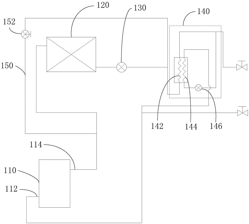
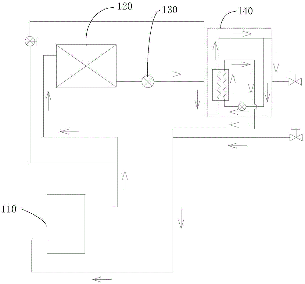
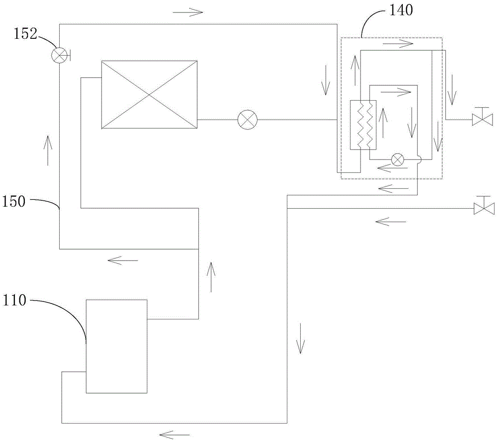
The invention discloses an outdoor unit refrigerant pipeline system, an air conditioner and a refrigeration control method for the air conditioner. The outdoor unit refrigerant pipeline system comprises a compressor, an outdoor heat exchange device and a first throttling device and further comprises a supercooling heat exchange device and a bypass. The supercooling heat exchange device comprises a first heat exchange assembly, a second heat exchange assembly and a second throttling device. One end of the bypass is connected with an exhaust opening of the compressor, and the other end of the bypass is connected with the first end of the first heat exchange assembly. The bypass is provided with a first electromagnetic valve. According to the outdoor unit refrigerant pipeline system, the air conditioner and the refrigeration control method for the air conditioner, the supercooling heat exchange device and the bypass are arranged, when low-temperature refrigerating is conducted, the first electromagnetic valve on the bypass is started, and the supercooling heat exchange device is directly connected with the exhaust opening of the compressor; then, refrigerants discharged out from the exhaust opening directly enter the supercooling heat exchange device which is used as a condenser, the condensing pressure can be improved effectively, and the operating stability of the outdoor unit refrigerant pipeline system is ensured.

Description

technical field [0001] The invention relates to the technical field of air conditioning, in particular to an outdoor unit refrigerant pipeline system, an air conditioner and a refrigeration control method for the air conditioner. Background technique [0002] Today, as the concepts of environmental protection and energy saving are increasingly accepted by everyone, many air-conditioning systems, especially large-capacity air-conditioning systems, have begun to use subcooling technology or jet enthalpy increasing technology to improve system capacity and energy efficiency. In these large-capacity air-conditioning systems, the capacity of a single system is usually ten or even dozens of horses. Especially for multi-connected systems, a system can be connected in parallel with modules of the same or different capacities, and there are multiple compressors inside the module. [0003] In these large-capacity air-conditioning systems, it is necessary not only to meet the capacity ...

Claims


Application Information

Patent Timeline
Patent Type & Authority Applications(China)
IPC IPC(8): F25B13/00F25B41/04F25B49/02F25B41/20
CPCF25B13/00F25B49/02F25B2700/2106F25B2700/1931F25B2600/25F25B2313/02741F25B41/20
Inventor 薛晓梁伯启董文涛王茹翰
Owner GD MIDEA HEATING & VENTILATING EQUIP CO LTD
Learn More