Reinforcement cage binding clamping fixture

A technology of reinforced skeleton and mould, which is applied in the application field of track slab processing reinforced skeleton

Pending Publication Date: 2016-06-01
SILVERY DRAGON PRESTRESSED MATERIALS CO LTD
View PDF3 Cites 3 Cited by
  • Summary
  • Abstract
  • Description
  • Claims
  • Application Information

AI Technical Summary

Problems solved by technology

[0003] The invention aims to solve the problem that the steel frame binding mold used in the production process of CRTSⅠ and CRTSⅡ track slabs can only meet the needs of one-dimensional steel bar positioning and binding, and provides a steel skeleton binding mold that can meet the needs of CRTS Ⅲ track slabs It is necessary to realize the criss-crossing two-dimensional steel bar positioning and binding requirements

Method used


Image

  • Reinforcement cage binding clamping fixture
  • Reinforcement cage binding clamping fixture

Examples


Embodiment Construction

[0014] Specific embodiments of the invention will be described in detail below in conjunction with the accompanying drawings.

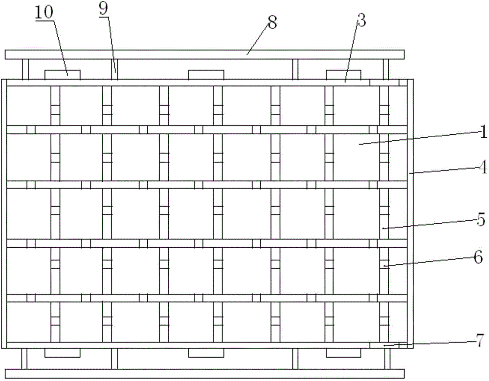
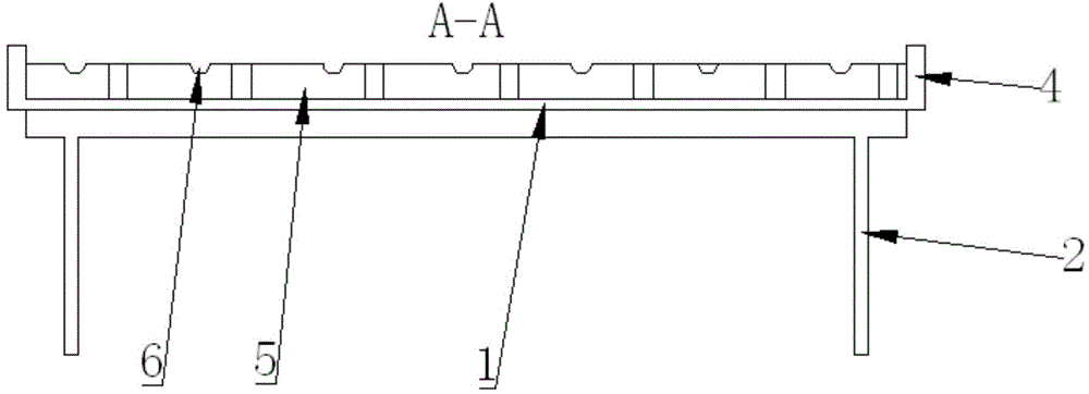
[0015] Such as Figure 1-2 As shown, the steel frame binding tire includes a bottom plate 1, a support seat 2, a vertical baffle and a positioning device. The support seat 2 is located below the bottom plate 1 and is used to support the bottom plate 1. The vertical baffle The board includes a transverse baffle 3 and a longitudinal baffle 4, the longitudinal baffles 4 are provided at the front and rear ends of the bottom plate 1, the transverse baffles 3 are provided on both sides of the bottom plate 1, and the positioning device is located at On the bottom plate 1, the positioning device is composed of several support plates 5 criss-crossing, the support plates 5 are provided with a number of limit card slots 6, and the two ends of the transverse baffle plate 3 are provided with grounding terminal slots 7 .

[0016] It also includes an auxiliary hoo...


PUM


Abstract

The invention provides a reinforcement cage binding clamping fixture. The reinforcement cage binding clamping fixture comprises a baseplate, a support base, a vertical baffle plate and a positioning device; the support base is positioned under the baseplate; the vertical baffle plate includes transverse baffle plates and longitudinal baffle plates; the longitudinal baffle plates are arranged at the front and back ends of the baseplate; the transverse baffle plates are arranged on two sides of the baseplate; the positioning device is positioned on the baseplate, and consists of multiple criss-cross support plates; multiple limiting clamping grooves are formed in the support plates; and grounding terminal grooves are formed in two ends of the transverse baffle plates. The reinforcement cage binding clamping fixture can satisfy the demand that CRTS III type rail plates need to realize positioned binding of criss-cross two-dimensional reinforcements; a clamping fixture body is formed by machining a steel material; the material is higher in hardness and small in deformation, so that the problem of incapability of accurately positioning the reinforcement position caused by long-time use of the reinforcement clamping fixture is effectively solved; the grounding terminal grooves are reserved in two ends of a side mold of the clamping fixture for preventing use accidents caused by no connection of grounding terminals by a reinforcement cage in the machining process; and lifting lugs are convenient for the movement of the clamping fixture.

Description

technical field [0001] The invention belongs to the application field of track slab processing steel skeleton, and in particular relates to a tying mold for CRTS III track slab steel skeleton binding. Background technique [0002] CRTSⅢ track slab is a new type of track slab with independent intellectual property rights in my country. Compared with CRTS Ⅰ and CRTS Ⅱ track slabs, its steel skeleton has evolved from the original one-dimensional structure of unidirectional steel bars to a two-dimensional skeleton structure intersecting horizontally and vertically. The tooling and molds used in the existing CRTSⅠ and CRTSⅡ track slab production processes can no longer meet the processing requirements of CRTS Ⅲ track slabs. In particular, the steel bar binding mold used in the steel bar skeleton binding process can only meet the needs of a single direction of steel bar binding. Contents of the invention [0003] The invention aims to solve the problem that the steel frame bindi...

Claims


Application Information

Patent Timeline
IPC IPC(8): B28B23/14
Inventor 王书信张慧毅艾铁岭
Owner SILVERY DRAGON PRESTRESSED MATERIALS CO LTD
Why Eureka
Try Eureka