
A tool for machining small holes at the root of hub outer splines

A technology of external splines and processing wheels, applied in metal processing equipment, metal processing machinery parts, positioning devices, etc., can solve the problems of low processing efficiency, easy damage of drill bits, unstable processing quality of small holes, etc., and achieve positioning processing Effect

Active Publication Date: 2017-10-24
ANHUI HELI CO LTD
View PDF9 Cites 0 Cited by
  • Summary
  • Abstract
  • Description
  • Claims
  • Application Information

AI Technical Summary

Problems solved by technology

Due to the small size of the external spline, the diameter of the small hole added at the root is generally about Φ3mm, and the holes of each group are distributed symmetrically in the circumferential direction, and the position of the spline has no corresponding relationship with other parts such as other holes on the workpiece, that is, the existing holes cannot be used Locate the spline position
The weight of the large-tonnage wheel reaches more than 60KG. At present, manual marking and radial drilling are mainly used. This method requires manual alignment and clamping. Its advantage is that it requires less equipment and does not require special tooling. Small hole processing at the root of the spline; the disadvantage is that it is not suitable for mass production and the processing efficiency is low. At the same time, manual clamping is labor-intensive, the quality of small hole processing is unstable, and the drill bit is easily damaged

Method used


Image

  • A tool for machining small holes at the root of hub outer splines
  • A tool for machining small holes at the root of hub outer splines
  • A tool for machining small holes at the root of hub outer splines

Examples


Embodiment Construction

[0023] The present invention will be further described below in conjunction with the accompanying drawings:

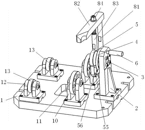
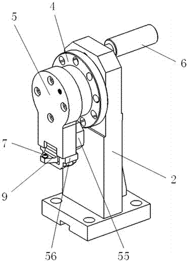
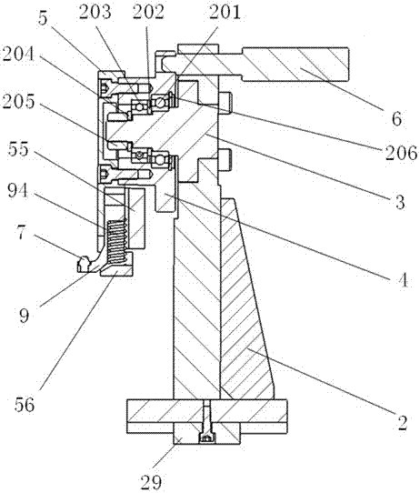
[0024] like figure 1 , figure 2 , image 3 The shown tooling for processing the small holes at the root of the outer spline of the wheel hub includes a base plate 1, and the base plate 1 is provided with a positioning device for positioning the wheel hub 100 and a support device for supporting the wheel hub 100 and forming a rolling fit with the wheel hub 100, The positioning device includes a positioning seat 2 fixed with the base plate 1, a rotating shaft 3 arranged on the positioning seat 2, a rotatable positioning flange 4 arranged on the rotating shaft 3, and a transition plate 5 fixed on the positioning flange 4. The central axis of 3 is consistent with the central axis of the hub 100. Between the positioning flange 4 and the positioning seat 2, there is a plug 6 that restricts the rotation of the positioning flange 4. The bottom of the transition plate 5 is p...


PUM


Abstract

The invention relates to a tool used for machining a small hole in a root of an external spline of a hub. The tool comprises a bottom plate. A positioning device used for positioning the hub and a supporting device used for supporting the hub are arranged on the bottom plate. The positioning device comprises a positioning seat fixed to the bottom plate, a rotating shaft arranged on the positioning seat, a positioning flange rotationally arranged on the rotating shaft and a transition plate fixed to the positioning flange. The central axis of the rotating shaft coincides with the central axis of the hub. A bolt used for limiting rotation of the positioning flange is arranged between the positioning flange and the positioning seat. A positioning pin is arranged at the bottom of the transition plate. The positioning pin and a key groove of the external spline of the hub are matched for positioning so as to limit the axial rotation of the hub. By means of the above technical scheme, the axial rotation of the hub is limited through the positioning pin on the transition plate, meanwhile, the transition plate and the positioning flange are fixedly connected, the circumferential rotation of the hub is driven through rotation of the positioning flange on the rotating shaft, and therefore positioning and machining of the small hole in the root of the external spline of the hub can be achieved.

Description

technical field [0001] The invention relates to a tool for processing small holes at the root of an external spline of a wheel hub. Background technique [0002] In order to improve the braking and heat dissipation effect of the forklift, it is necessary to add several groups of small holes at the root of the external spline of the forklift hub to facilitate the rapid transmission of oil pressure and take away the heat generated by braking. Due to the small external spline, the diameter of the small hole added at the root is generally about Φ3mm, each group of holes is distributed symmetrically in the circumferential direction, and the position of the spline has no positional correspondence with other holes and other components on the workpiece, that is, the existing holes cannot be used. Locate the spline position. The weight of the large-tonnage hub is more than 60KG. At present, the main methods of manual marking and radial drilling machine processing are used. This meth...

Claims


Application Information

Patent Timeline
Patent Type & Authority Patents(China)
IPC IPC(8): B23Q3/06
CPCB23Q3/062
Inventor 袁兵昌郑吉先谢云张琴
Owner ANHUI HELI CO LTD
Learn More