
Waste heat and waste pressure type water source heat pump system applying boiler smoke waste heat

A technology of water source heat pump and boiler flue gas, which is applied in the fields of energy recovery and utilization equipment, boilers, and water source heat pumps. Utilization rate, improved heat transfer efficiency, and small heat loss effects

Inactive Publication Date: 2016-05-25
JIANGSU UNIV
View PDF3 Cites 3 Cited by
  • Summary
  • Abstract
  • Description
  • Claims
  • Application Information

AI Technical Summary

Problems solved by technology

Conventional heat exchangers have low heat transfer temperature and pressure, large volume, high investment costs, or because of long heat transfer process, large resistance, sharp increase in driving power consumption, high operating costs, or complex manufacturing and difficult maintenance. Or its application in waste heat recovery is limited due to corrosion, fouling, critical equipment life, etc.
[0004] At present, the recovery of waste heat from flue gas produced by boilers mainly uses the sensible heat of water to recover waste heat, and the air preheater uses the sensible heat of air to recover waste heat, in which the sensible heat of water is used to recover flue gas The economizer with waste heat has a large water flow, high power consumption of the water pump, low heat transfer coefficient, and poor economy; and as long as a water pipe breaks, it will affect the normal operation of the boiler and pose a safety hazard; in addition, when the inlet water temperature is low, Some economizer pipelines are often lower than the acid dew point temperature, resulting in pipeline acid corrosion; the main disadvantage of the air preheater that uses the sensible heat of the air to recover waste heat is: whether it is a partitioned air The heater, the air channel and the flue gas channel must be closely connected together, the engineering layout is difficult, and there are also phenomena such as air and flue gas mixing; moreover, due to the low heat transfer coefficient of the gas and the large heat exchanger, the flue is also Very large; in addition, when the inlet air temperature is low, the heat exchanger corrosion caused by the air preheater lower than the acid dew point temperature often occurs

Method used


Image

  • Waste heat and waste pressure type water source heat pump system applying boiler smoke waste heat

Examples


Embodiment Construction

[0035] The present invention will be further described below in conjunction with specific embodiment:

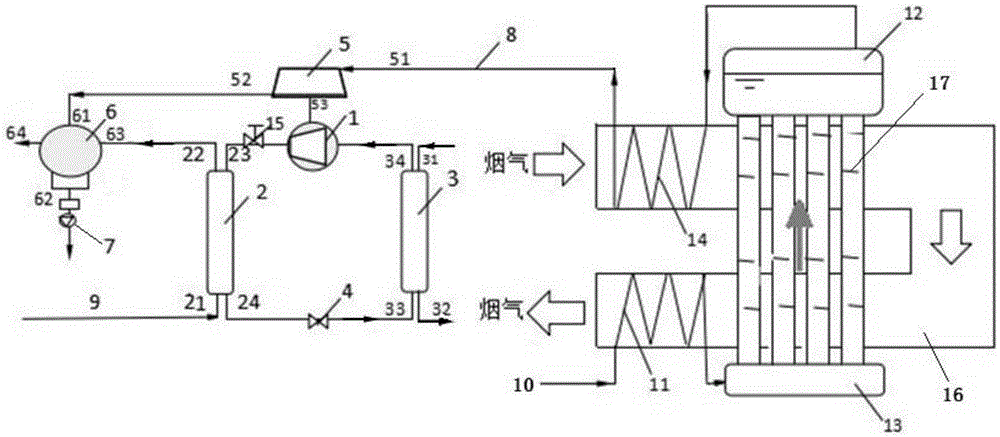
[0036] Such as figure 1 As shown, a waste heat and pressure water source heat pump system utilizing boiler flue gas waste heat, including a water source heat pump system and a waste heat utilization system of a natural circulation waste heat boiler;

[0037]The waste heat utilization system of the natural circulation waste heat boiler includes a steam passage 8, a water supply pipe 10, an economizer 11, a steam drum 12, a second evaporator 13, a superheater 14 and a flue gas pipeline 16, and the economizer 11 is wound around On the outer wall of the outlet of the flue gas pipeline 16, the superheater 14 is wound on the outer wall of the inlet of the flue gas pipeline 16; the water supply pipe 10 is connected to the inlet of the economizer 11, and the The outlet is connected to the inlet of the second evaporator 13 through a pipeline A; the outlet of the second evaporator 13...


PUM


Abstract

The invention provides a waste heat and waste pressure type water source heat pump system applying boiler smoke waste heat. The water source heat pump system comprises a water source heat pump system and a waste heat utilizing system of a natural circulating waste heat boiler. The waste heat utilizing system of the natural circulating waste heat boiler comprises a steam way, a water supply pipe, a coal economizer, a steam bag, a second evaporator, an overheater and a smoke pipeline. The water source heat pump system comprises a compressor, a condenser, a first evaporator, an expansion valve, a steam turbine, a steam and water heat exchanger, a condensate water pump, a circulating water return pipe and a flow control valve. By means of the waste heat and waste pressure type water source heat pump system, waste gas of the natural circulating waste heat boiler can be effectively utilized, and the energy utilization rate is increased.

Description

technical field [0001] The invention belongs to the technical field of energy recovery and utilization equipment, relates to the technical field of boilers and water source heat pumps, in particular to a waste heat and pressure water source heat pump system utilizing waste heat of boiler flue gas. Background technique [0002] The efficient utilization of energy and energy saving and environmental protection have become the key issues that determine whether human society can develop sustainably and rapidly in the long term, and are increasingly being paid attention to by people. In today's society, water source heat pump technology develops rapidly and is widely used. The water source heat pump system consumes a small amount of electric energy to drive the compressor to run to form a heat pump cycle, and converts low-grade heat energy with a low temperature into a high-grade heat energy with a high temperature that can be used for production and life. In some industrially de...

Claims


Application Information

Patent Timeline
IPC IPC(8): F25B27/02F25B30/06F01K27/02
CPCY02A30/274F25B27/02F01K27/02F25B30/06
Inventor 王爽夏禛曹斌王谦胡亚敏林骁驰孙超群
Owner JIANGSU UNIV
Learn More