
Turbofan engine air intake duct anti-icing structure and anti-icing method

A technology of turbofan engine and air intake, which can be used in machines/engines, mechanical equipment, jet propulsion devices, etc., and can solve problems such as engine performance degradation

Active Publication Date: 2016-05-25
AECC COMML AIRCRAFT ENGINE CO LTD
View PDF3 Cites 3 Cited by
  • Summary
  • Abstract
  • Description
  • Claims
  • Application Information

AI Technical Summary

Problems solved by technology

[0004] However, hot gas anti-icing must be bleed air from the engine core (generally high-pressure compressor bleed air), which will inevitably reduce engine performance. Therefore, how to maximize anti-icing requirements while meeting the engine intake Utilization of ice and hot air, minimizing the amount of engine bleed air is the key to air anti-icing design of civil turbofan engines

Method used


Image

  • Turbofan engine air intake duct anti-icing structure and anti-icing method
  • Turbofan engine air intake duct anti-icing structure and anti-icing method
  • Turbofan engine air intake duct anti-icing structure and anti-icing method

Examples


Embodiment Construction

[0033] The present invention will be further described below in conjunction with specific embodiment and accompanying drawing, set forth more details in the following description so as to fully understand the present invention, but the present invention can obviously be implemented in many other ways different from this description, Those skilled in the art can make similar promotions and deductions based on actual application situations without violating the connotation of the present invention, so the content of this specific embodiment should not limit the protection scope of the present invention.

[0034] In the following description, the present invention is described with reference to various examples. One skilled in the art will recognize, however, that the various embodiments may be practiced without one or more of the specific details, or with other alternative and / or additional methods, materials, or components. In other instances, well-known structures, materials, ...


PUM

PropertyMeasurementUnit
Widthaaaaaaaaaa

Abstract

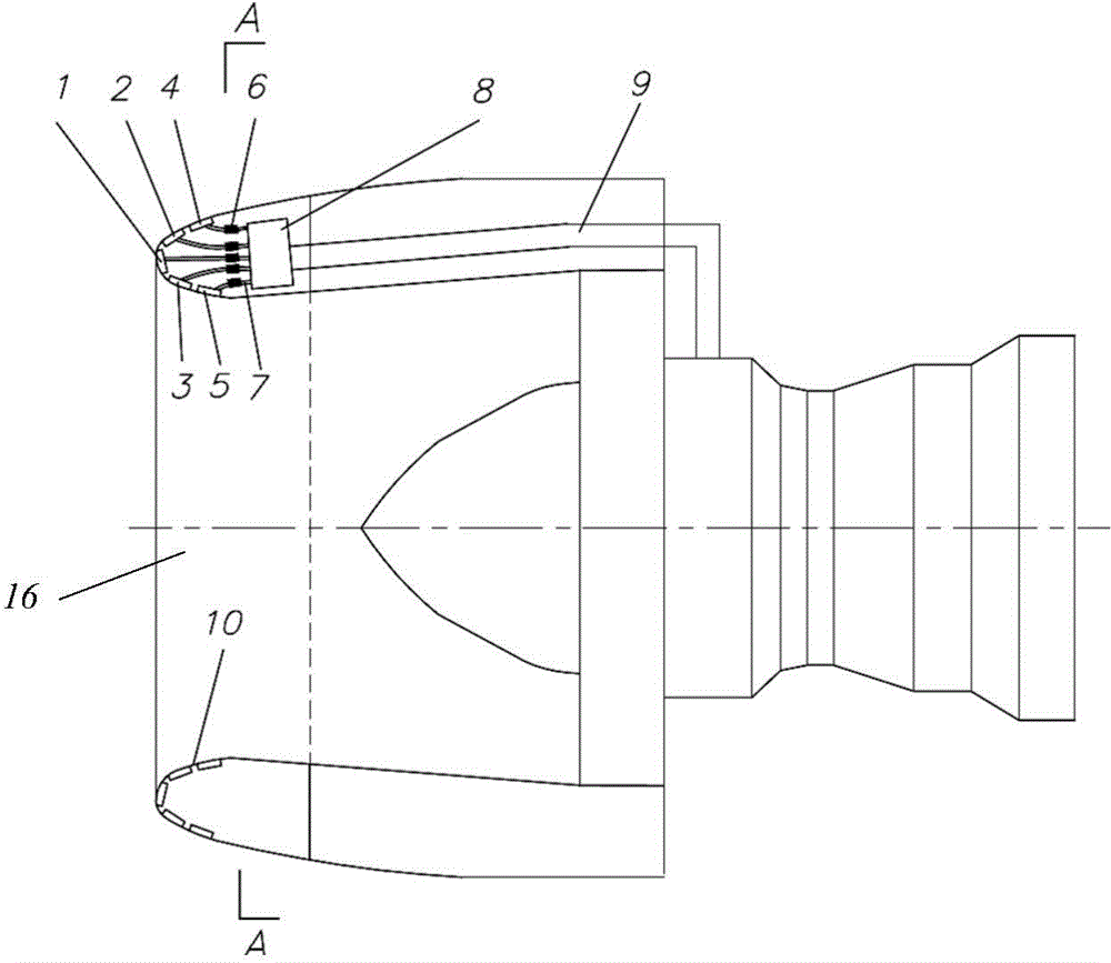
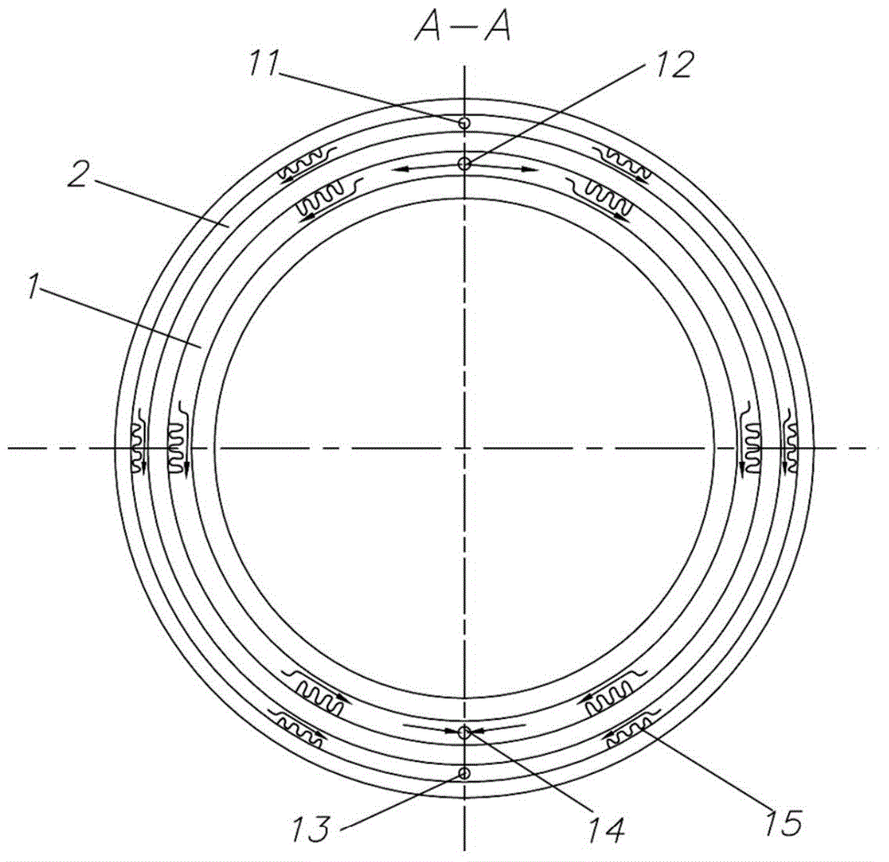
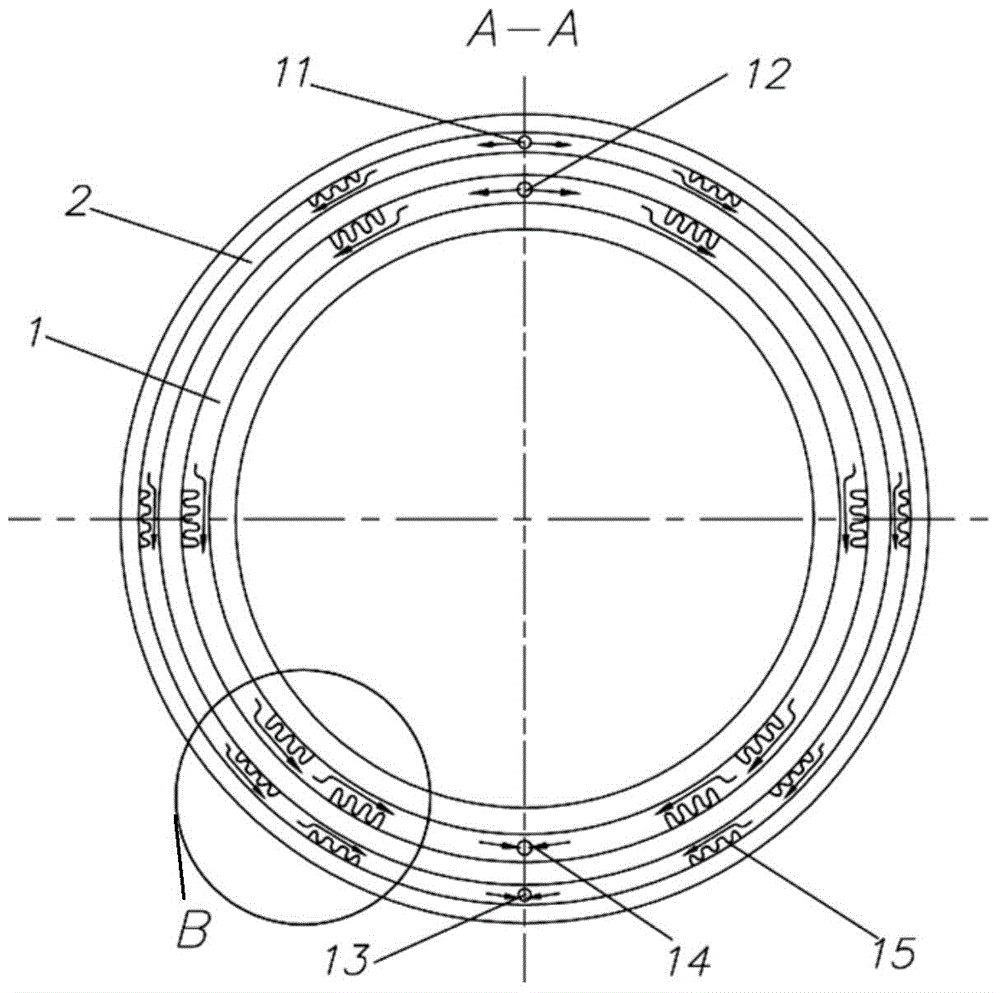
The invention relates to a turbofan engine air intake duct anti-icing structure and an anti-icing method. The turbofan engine air intake duct anti-icing structure is characterized by comprising an air-entrainment total pipe of an engine core machine, a collector box connected with the air-entrainment total pipe, several heating branch pipes divided from the collector box, and several anti-icing ring chamber arranged in an anti-icing part of an air intake duct port, branch pipe valves are arranged on the heating branch pipes, anti-icing hot gas is introduced into the air-entrainment total pipe and flows to the collector box, then is optionally distributed to at least a part of the heating branch pipes according to the opening condition from the collector box, then is conveyed to the corresponding anti-icing ring chamber through the heating branch pipe, and is discharged from an air exhaust port of the anti-icing ring chamber.

Description

technical field [0001] The invention relates to an anti-icing structure and an anti-icing method for an air inlet of a turbofan engine. Background technique [0002] The civil turbofan engine is the power plant of the current large civil aviation airliner, and its inlet icing problem is one of the key factors affecting the performance and safety of the entire power plant. Because the air in the intake duct is in a suction state, the airflow velocity increases and the static temperature decreases, making the component extremely easy to freeze. The icing of the intake duct will change the aerodynamic characteristics of the intake system, increase the flow resistance, make the distribution of the intake air field uneven, and even cause air flow distortion, which will affect the working stability of the engine, and may cause the engine to stall in severe cases. The icing of the intake duct will also cause the melted and fallen ice to be inhaled by the engine, causing serious pr...

Claims


Application Information

Patent Timeline
IPC IPC(8): F02C7/047
Inventor 陈俊邓阳
Owner AECC COMML AIRCRAFT ENGINE CO LTD
Learn More