Unloading system of two-way feeding ore bin

A technology of ore silo and material feeding, which is applied in the field of two-way feeding ore silo unloading system, can solve the problems of increased project investment and operating cost, large impact of raw materials on the chute, and crowded plane layout on the silo, so as to reduce project investment and Production and operation costs, compact layout, and convenient crossing

Active Publication Date: 2016-05-25
HUATIAN ENG & TECH CORP MCC
View PDF8 Cites 5 Cited by
  • Summary
  • Abstract
  • Description
  • Claims
  • Application Information

AI Technical Summary

Problems solved by technology

At present, more than two belt conveyors are arranged on many warehouses, the purpose is to serve as backup for each other and increase the unloading capacity. Since each unloading truck has two walking tracks, the distance between the two belt conveyors is relatively large. , the layout of the warehouse is relatively crowded; if the warehouse needs to store many types of raw materials, many enterprises use double-row warehouses. The silo on one side cannot be interchanged when unloading on the silo; in order to realize the interchange between the systems before entering the silo, the general belt conveyor conveying system enters the silo from one end of the silo, so , the number of transshipment is more, the transportation distance is increased, and the project investment and operation cost are increased; the unloading truck can be used as a safe ladder for the belt conveyor below it, but it needs to cross two unloading trucks from one side of the warehouse to the other. Feeder trucks, so the span time is longer; when the unloading truck directly unloads the raw materials through the chute into the warehouse, the drop is large, the raw materials have a greater impact on the chute, and the impact surface of the chute is severely worn, requiring frequent maintenance, which affects production and increases maintenance costs.

Method used


Image

  • Unloading system of two-way feeding ore bin
  • Unloading system of two-way feeding ore bin
  • Unloading system of two-way feeding ore bin

Examples


Embodiment 1

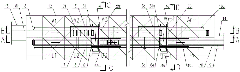
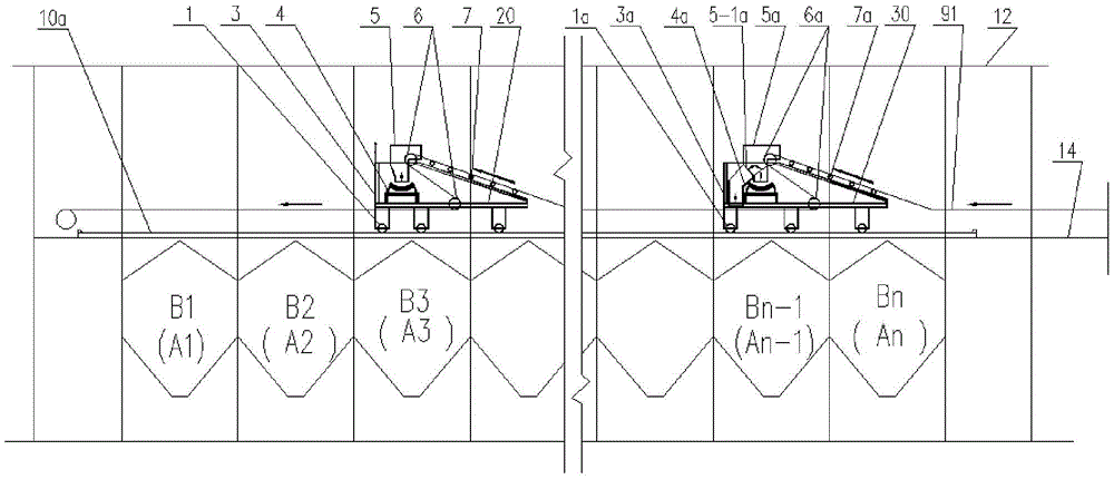
[0035] Such as Figure 1-5 As shown, the two-way feeding ore bunker unloading system of this embodiment includes two rows of ore bins 12, two corridors 13, 14 arranged at both ends of the two rows of ore bins, and two corridors 13, 14 respectively connected Belt conveyors 8, 9 and two bi-directional distributing and unloading vehicles 20, 30 matched with the two belt conveyors; the two belt conveyors 8, 9 are arranged in parallel, and the two belt conveyors 8, 9 run in opposite directions ;

[0036] Two-way distributing and unloading vehicles 20, 30 include vehicle frames 3, 3a, distributing devices and unloading devices arranged on the vehicle frames and reversible belt conveyors 4, 4a; Traveling mechanism 1, 11, 1a, 11a; the frame includes two sub-frames facing oppositely, and the tails of the two sub-frames are connected to each other; the material distribution device includes material distribution funnels 51, 5a, idler roller groups 6a, 61 and redirection Drum sets 7a, 7...

Embodiment 2

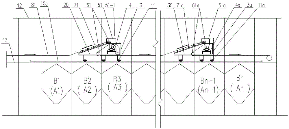
[0055] On the basis of the above-mentioned embodiment, the reversing roller group 6, 61, 6a, 61a includes the first roller arranged in the discharge funnel or the distribution funnel and the second roller arranged in front of the first roller; It includes several idlers arranged in sequence from front to back and from low to high.

[0056] The second roller is arranged on the front and lower side of the first roller, so that the belt conveyor belt between the first roller and the second roller can be at a certain angle to the vertical direction, so that the materials can be easily unloaded into the distribution funnel 5a, 51 or unloaded. Material funnel 5,51a, supporting roller group 7,71,7a, 71a are arranged from front to back, from low to high, so that the belts of belt conveyors 8,9 can be raised upwards at first before unloading, which is the second improvement. Provide adequate position to the pulley for belt redirection and unloading.

Embodiment 3

[0058] On the basis of the above embodiments, each idler roller and the first roller of the idler roller group 7, 71, 7a, 71a have a common cut surface, and the common cut surface is above each idler roller and the first roller.

[0059] Each idler and the first roller have a common cut surface on the upper side, so that the belt of the belt conveyor is arranged along the common cut surface, which can reduce the direction change of the belt conveyor 8, 9, and the reduction of the direction change can reduce resistance and save energy. energy.


PUM


Abstract

The invention discloses an unloading system of a two-way feeding ore bin and aims to solve the problem that in the prior art, a two-way feeding ore bin is loose in structure. The unloading system of the two-way feeding ore bin comprises a belt type conveyor and two material distributing and unloading carts matched with the belt type conveyors; each material distributing and unloading cart comprises a cart frame and a material distributing device and a material unloading device which are opposite in direction; each material distributing device comprises a material distributing hopper, and each material distributing funnel comprises two unloading outlets and a material distributing plate arranged at the intersecting position of the two unloading outlets; each unloading device comprises an unloading funnel, the material distributing funnels are flush with the material unloading funnels, and a reversible belt type conveyor is arranged below the material distributing funnels and the material unloading funnels; the belt conveyor is matched with one material distributing device and one material unloading device, and the material distributing devices are arranged in front of the material unloading devices. The unloading system is compact in structure, good in production interchangeability, high in production safety, less in one-time investment and low in operation and maintenance cost.

Description

technical field [0001] The invention relates to a two-way feeding ore bunker unloading system. Background technique [0002] The bin loading and unloading system is mainly used in the field of bulk material transportation, and the working conditions are relatively harsh. At present, the mine loading and unloading system mainly includes an unloading car and a belt conveyor. The unloading car is a mobile device that rides on a belt conveyor. The truck unloads various bulk materials on the belt conveyor into different bins through the chute, and the drop is large when unloading. The unloading truck mainly includes: traveling mechanism, frame, unloading hopper, reversing roller group, idler roller group etc. At present, more than two belt conveyors are arranged on many warehouses, the purpose is to serve as backup for each other and increase the unloading capacity. Since each unloading truck has two walking tracks, the distance between the two belt conveyors is relatively larg...

Claims


Application Information

Patent Timeline
IPC IPC(8): B65G47/18B65G47/34
CPCB65G47/18B65G47/34
Inventor 张立功
Owner HUATIAN ENG & TECH CORP MCC
Why Eureka
Try Eureka