
Pneumatic tire

一种充气轮胎、胎面部的技术,应用在轮胎零部件、轮胎胎面/胎面花纹、运输和包装等方向,能够解决堵塞等问题,达到排泥性能优异的效果

Active Publication Date: 2016-05-25
TOYO TIRE & RUBBER CO LTD
View PDF6 Cites 6 Cited by
  • Summary
  • Abstract
  • Description
  • Claims
  • Application Information

AI Technical Summary

Problems solved by technology

If such tires are used to drive on muddy ground, etc., there is a possibility that mud, etc. will penetrate into the grooves and clog them.

Method used


Image

  • Pneumatic tire
  • Pneumatic tire
  • Pneumatic tire

Examples


Embodiment Construction

[0066] Hereinafter, embodiments of the present invention will be described with reference to the drawings. In addition, the following description is merely an illustration in nature, and is not intended to limit the present invention, its application, or its use. In addition, the drawings are schematic diagrams, and ratios of dimensions and the like are different from actual ones.

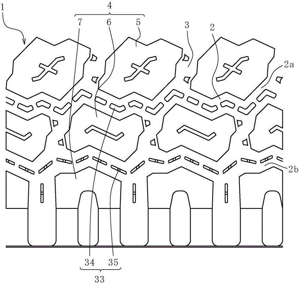
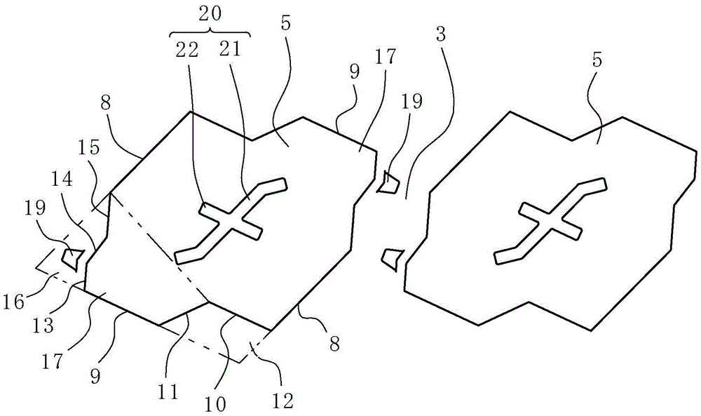
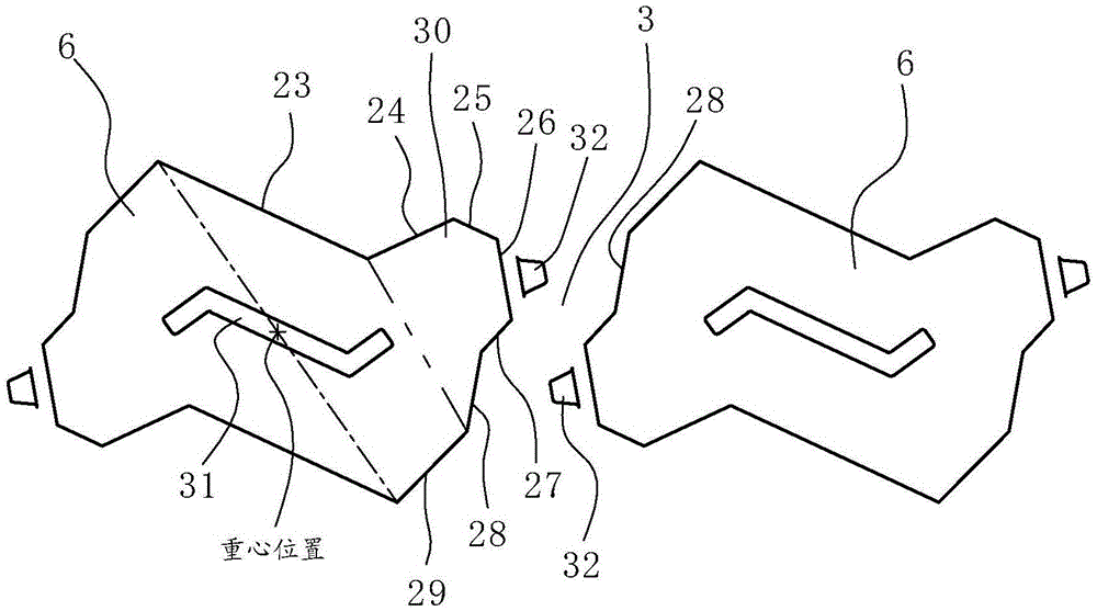
[0067] figure 1 It is a partially developed view of the tread portion 1 in this embodiment. Formed on the tread portion 1 are: a plurality of annular main grooves 2 extending continuously in the tire circumferential direction; and a plurality of lateral grooves 3 intersecting the main grooves 2 and extending in the tire width direction. Here, the main grooves 2 are zigzag-shaped, and four are formed at predetermined intervals in the tire width direction (only the first groove 2a and the second groove 2b on one side are shown, and the other two are omitted from the figure). Show). In addition, t...


PUM


Abstract

The invention aims to provide pneumatic tire with excellent spoil disposal performance. On a tread portion (1), a plurality of blocks (4) are formed by a plurality of main grooves (2) annularly continuously extending in a tire circumferential direction, and a plurality of transverse grooves (3) extending in a tire width direction, intersecting these main grooves (2). Each block has projections (19) on side surfaces (18), which form each transverse groove (3), at corner regions thereof.

Description

technical field [0001] The present invention relates to a pneumatic tire. Background technique [0002] Conventionally, a pneumatic tire is known as a pneumatic tire in which a protrusion is formed on at least one groove wall of widthwise grooves in a tread center portion (for example, refer to Patent Document 1). [0003] However, the protrusions are effective only in terms of anti-stone trapping performance, that is, performance in preventing small stones on the road surface from being caught in the groove portion. When such tires are used to travel on muddy ground, mud or the like may intrude into and clog the grooves. At this time, the traction performance of the tire may deteriorate, or lateral slip may occur during cornering. [0004] Prior art literature: [0005] patent documents [0006] Patent Document 1: Japanese Patent Laid-Open No. 2012-148678 Contents of the invention [0007] The problem to be solved by the invention [0008] An object of the present i...

Claims


Application Information

Patent Timeline
Patent Type & Authority Applications(China)
IPC IPC(8): B60C11/04B60C11/13
CPCB60C11/042B60C11/1307B60C2011/1338B60C11/032B60C11/11B60C2011/0346B60C2011/1361B60C2011/0341
Inventor 藤冈刚史
Owner TOYO TIRE & RUBBER CO LTD
Learn More