Eureka AIR delivers breakthrough ideas for toughest innovation challenges, trusted by R&D personnel around the world.

Construction method for integrally forming large cast-in-place thin-wall high pier through stiff skeleton reinforcement cage

A rigid skeleton, integral forming technology, applied in the erection/assembly of bridges, bridges, buildings, etc., can solve the problems of large investment in steel, high cost, low precision of high pier main reinforcement, and achieve accurate overall verticality and reinforcement position. Accurate and reduce the effect of steel input

Inactive Publication Date: 2016-05-18
SHANGHAI JIASHI (GROUP) CO LTD
View PDF5 Cites 7 Cited by
  • Summary
  • Abstract
  • Description
  • Claims
  • Application Information

AI Technical Summary

Problems solved by technology

However, the traditional rigid frame is difficult to control the positioning of the main reinforcement of the high pier, so that the accuracy of the binding of the main reinforcement of the high pier is low
Moreover, the traditional rigid frame needs to invest a large amount of steel to ensure the overall stability of the steel cage during hoisting, and the cost of steel is large; the traditional rigid frame positioning device usually uses permanent positioning steel plates, and the cost is relatively high; and the steel joints and positioning holes The edge constraints affect the removal of the positioning frame. During the binding installation and concrete pouring process, the vertical steel bars will inevitably move or tilt, which will cause the upper joint and the edge of the positioning hole to be tightly squeezed, making it difficult to remove the positioning frame.

Method used


Image

  • Construction method for integrally forming large cast-in-place thin-wall high pier through stiff skeleton reinforcement cage
  • Construction method for integrally forming large cast-in-place thin-wall high pier through stiff skeleton reinforcement cage
  • Construction method for integrally forming large cast-in-place thin-wall high pier through stiff skeleton reinforcement cage

Examples


Embodiment Construction

[0033] The steel structure welding process, bolt connection construction process, formwork setting process, and concrete pouring construction process in this embodiment will not be described in detail in this implementation, and the embodiments of the present invention related to structures will be emphatically described.

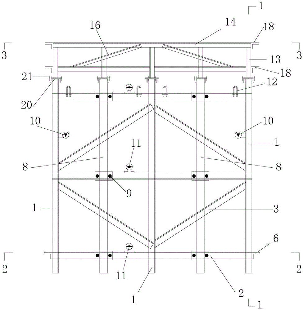
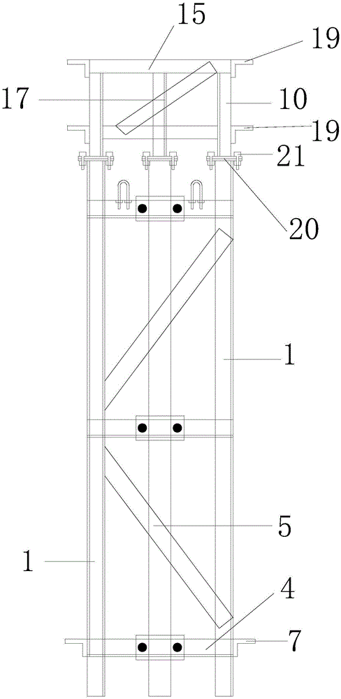
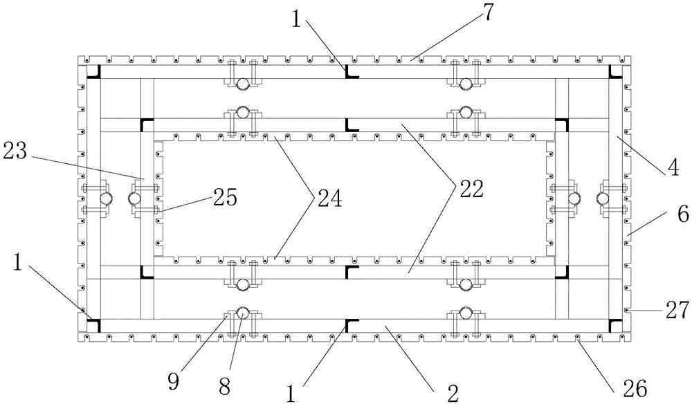
[0034] figure 1 It is a schematic diagram of the structure of a large cast-in-place thin-walled high pier integrally formed by the rigid skeleton steel cage of the present invention. refer to figure 1 As shown in the figure, the large-scale cast-in-place thin-walled high pier structure of the rigid skeleton steel cage integrally formed in the present invention mainly includes: rigid skeleton vertical rod 1; rigid skeleton outer layer horizontal cross bar A2; rigid skeleton shear brace A3; rigid skeleton Frame outer horizontal bar B4; stiff frame shear brace B5; outer positioning angle steel A6; outer positioning angle steel B7; steel pipe 8; fastener 9; in...


PUM


Abstract

The invention relates to a construction method for integrally forming a large cast-in-place thin-wall high pier through a stiff skeleton reinforcement cage. The construction method includes the main construction steps of (1) stiff skeleton erection, (2) locating frame installation, (3) locating frame and stiff skeleton butt joint, (4) reinforcing steel bar binding and forming, (5) lifting frame installation, (6) overall lifting and butt joint, (7) auxiliary facility disassembly, and (8) formwork construction. A structure related to the construction method has the beneficial effects that binding is convenient; the construction efficiency is high; a stiff skeleton can be partially disassembled and recycled; accurate localization of reinforcing steel bars is guaranteed and a double-layer locating frame is easy to disassemble; the reinforcing steel bars can be integrally formed and lifted for butt joint in a segmental manner; reinforcing steel bar binding time is shortened; the upper section and lower section concrete pouring period difference is reduced; and the economic and technological benefits are good.

Description

technical field [0001] The invention relates to a rigid positioning skeleton system for installing a cast-in-place thin-walled high pier steel cage, in particular to a construction method for integrally forming a large cast-in-situ thin-walled high pier with a rigid skeleton steel cage. Background technique [0002] In bridge engineering, high pier construction is an extremely important part. In order to ensure the construction quality and safety of high pier construction, the use of stiff skeleton for construction is the most commonly used method. The rigid skeleton plays an important role in the fixation of steel bars and the consolidation of formwork. Specifically, after the rigid skeleton is added, due to the high rigidity of the rigid skeleton, the steel bars and formwork can be fixed on the rigid skeleton, thereby preventing the overall tilting of the steel skeleton and the occurrence of formwork collapse accidents. The safety belt is fixed by the rigid frame, which p...

Claims


Application Information

Patent Timeline
Patent Type & Authority Applications(China)
IPC IPC(8): E01D21/00
CPCE01D21/00
Inventor 李发林徐伟陈添鹤陈国平张超付爱平姜海龙黄健
Owner SHANGHAI JIASHI (GROUP) CO LTD
Why Eureka
Eureka Blog
Learn More