
Bi-metal pipeline and pipe fitting beveling method and bi-metal pipeline and pipe fitting assembly

A bimetallic pipe and pipe bevel technology, applied in the direction of pipes/pipe joints/fittings, metal processing equipment, pipes, etc., can solve the problems of reduced corrosion resistance of welds, changes in weld materials, and misalignment, etc., to avoid The effects of weld leakage, ensuring weld quality and pipeline operation safety, and avoiding serious problems

Inactive Publication Date: 2016-05-18
ZHENGZHOU WANDA HEAVY IND CO LTD
View PDF7 Cites 1 Cited by
  • Summary
  • Abstract
  • Description
  • Claims
  • Application Information

AI Technical Summary

Problems solved by technology

[0002] In recent years, with the rapid development of petroleum, natural gas, chemical industry, and ship development, the corrosion environment of pipelines has put forward higher and more stringent corrosion resistance requirements for pipelines. At present, most of them are bimetallic pipelines, which are resistant to corrosion and wear. Especially strong, suitable for marine, petroleum, chemical, pharmaceutical, electric power, natural gas transmission, aerospace industry, shipbuilding, etc., but the bimetallic pipeline is divided into two parts: the base layer and the layered layer. When the diameter difference of the pipe fittings is within the standard range And when the misalignment of the welding joints of the pair reaches 0-4mm, the thickness of the cladding layer is only 2-4mm. There are 0-2mm, and sometimes due to the influence of positive and negative values, the misalignment is serious, and the effective thickness of the cladding layer is 0, which causes the welding of the cladding layer and the base layer, causing the leakage of the girth weld of the pipeline to be very serious after operation, and resulting in weld seams The material changes, and the corrosion resistance of the weld is also greatly reduced
For example, in the standard, when the nominal diameter of the pipe fitting is 650-750, the inner diameter of the end is ±2.0. Within the standard range, there are exactly 4 values ​​between +2 and -2, and the cladding thickness is only 2-4mm. It is easy to cause wrong edge phenomenon

Method used


Image

  • Bi-metal pipeline and pipe fitting beveling method and bi-metal pipeline and pipe fitting assembly

Examples


Embodiment Construction

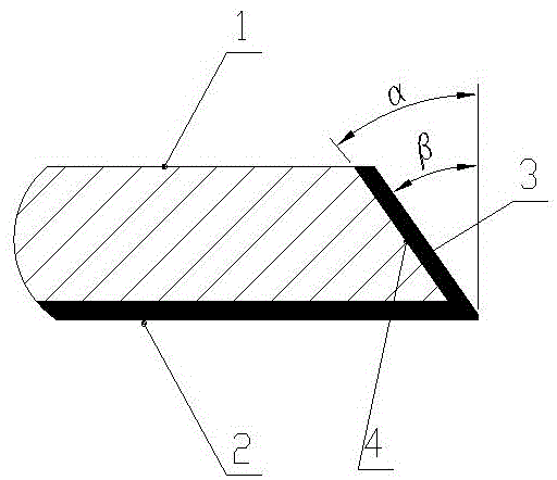
[0024] Such as figure 1 As shown, the bevel method for bimetallic pipes and pipe fittings of the present invention is used for bimetallic pipes and bimetallic pipe fittings. Both bimetallic pipes and bimetallic pipe fittings include a base layer 1 and a cladding layer 2. The material of the base layer 1 is carbon steel, alloy One of steel and stainless steel, the cladding layer 2 is made of nickel-based alloy or stainless steel,

[0025] Groove method:

[0026] In the first step, the first groove processing is performed on the base layer 1 and the layer 2 of the end face of the bimetallic pipe or bimetallic pipe fitting, and the degree α of the groove is 30-37.5 degrees;

[0027] In the second step, surfacing welding is performed on the processed groove end face 4 to form a surfacing layer, and the material of the surfacing layer is nickel-based alloy or stainless steel. The surfacing layer formed at this time is called the initial surfacing layer;

[0028] The third step i...


PUM

PropertyMeasurementUnit
Thicknessaaaaaaaaaa

Abstract

A bi-metal pipeline and pipe fitting beveling method is used for a bi-metal pipeline and a bi-metal pipe fitting. The bi-metal pipeline and the bi-metal pipe fitting each comprise a base layer and a composite layer. Each base layer is made of one of carbon steel, alloy steel and stainless steel. Each composite layer is made of nickel-based alloy or stainless steel. The beveling method comprises the first step that primary beveling is conducted on the base layer and the composite layer of the end face of the bi-metal pipeline or the bi-metal pipe fitting, and the end face is called a beveled end face after primary beveling. The problem of circular seam leakage caused by misalignment can be solved, and the circular seam installation quality is guaranteed.

Description

technical field [0001] The invention relates to the field of pipelines, in particular to a bimetallic pipeline and pipe fittings. Background technique [0002] In recent years, with the rapid development of petroleum, natural gas, chemical industry, and ship development, the corrosion environment of pipelines has put forward higher and more stringent corrosion resistance requirements for pipelines. At present, most of them are bimetallic pipelines, which are resistant to corrosion and wear. Especially strong, suitable for marine, petroleum, chemical, pharmaceutical, electric power, natural gas transmission, aerospace industry, shipbuilding, etc., but the bimetallic pipeline is divided into two parts: the base layer and the layered layer. When the diameter difference of the pipe fittings is within the standard range And when the misalignment of the welding joints of the pair reaches 0-4mm, the thickness of the cladding layer is only 2-4mm. There are 0-2mm, and sometimes due ...

Claims


Application Information

Patent Timeline
IPC IPC(8): B23P15/00F16L9/02B23K33/00
CPCB23P15/00B23K33/004B23K33/006F16L9/02
Inventor 何清张付峰袁希海许江新李怀刚白杨任保剑康佳音
Owner ZHENGZHOU WANDA HEAVY IND CO LTD
Learn More