Transformer substation fence rod fixing support
A technology for fixing brackets and fence poles, which is applied in the direction of fences, building types, buildings, etc., and can solve problems such as difficult handling, large impact area, and fence pole deviation
- Summary
- Abstract
- Description
- Claims
- Application Information
AI Technical Summary
Problems solved by technology
Method used
Image
Examples
Embodiment 1
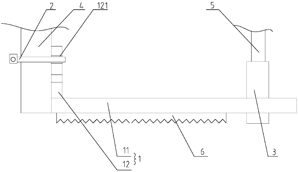
[0025] refer to figure 1 , shows a substation fence pole fixing bracket, including a bracket 1 and a binding piece, the bracket 1 is provided with a fence fixing pile 3, and the fence fixing pile 3 is provided with a jack, and the bottom of the fence pole 5 is inserted into the jack Among them, the binding piece binds the support 1 to the support body 4 in the substation, thereby fixing the support body 1, and the support body 4 can be an equipment foot or a cement column in the substation.
[0026] In this embodiment, the binding piece includes a clamp 2, which is also called a throat clamp. A clamp binding groove 121 for connecting the clamp 2 is provided on the bracket 1. The clamp binding groove 121 prevents the clamp 2 from The bracket 1 is detached, and the hoop 2 is tightened with metal threads to bind the bracket 1 to the branch body 4 in the substation. The fixation is firm and reliable, and the lateral bearing capacity is high.
[0027] Specifically, the bracket 1 i...
Embodiment 2
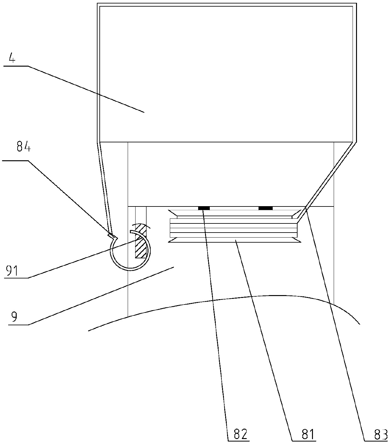
[0033] A substation fence pole fixing bracket, including a bracket and a binding piece, the bracket is provided with a fence fixing pile, the fence fixing pile is provided with a socket, the bottom of the fence pole is inserted into the socket, and the binding piece binds the bracket On the support body in the substation, the structure of the support in this embodiment is similar to that of Embodiment 1, and the structure of the support will not be repeated here. refer to image 3 The difference between this embodiment and Embodiment 1 is that the binding member includes a locking member, a winding device and a binding rope 83, the winding device is arranged on the bracket 9, one end of the binding rope 83 is wound on the winding device, and the binding rope The other end of 83 bypasses the support body 4 and connects to the bracket 1 through the locking piece. Therefore, it is convenient to bind the bracket 9 and the support body 4 .
[0034] In this embodiment, the locking...
PUM
 Abstract
Description
Claims
Application Information
 - R&D Engineer
- R&D Manager
- IP Professional
- Industry Leading Data Capabilities
- Powerful AI technology
- Patent DNA Extraction
Browse by: Latest US Patents, China's latest patents, Technical Efficacy Thesaurus, Application Domain, Technology Topic, Popular Technical Reports.
© 2024 PatSnap. All rights reserved.Legal|Privacy policy|Modern Slavery Act Transparency Statement|Sitemap|About US| Contact US: help@patsnap.com


