
Multifunctional solid waste treatment device and solid waste treatment method thereof

A solid waste, multi-functional technology, used in combustion methods, dehydration/drying/concentrated sludge treatment, lighting and heating equipment, etc., can solve the problems of incomplete combustion, inability to coordinate, incomplete treatment, etc., and achieve low energy waste. , functional diversification, to achieve the effect of waste utilization

Active Publication Date: 2016-05-04
深鹏环保工程有限公司
View PDF6 Cites 11 Cited by
  • Summary
  • Abstract
  • Description
  • Claims
  • Application Information

AI Technical Summary

Problems solved by technology

Due to the lack of a large amount of capital investment and the non-standard construction of the landfill, a large amount of landfill leachate outside the landfill polluted the underground (surface) water source, seriously affecting the health of the surrounding villagers
With the financial support of the state, although some small-scale garbage incinerators and gasifiers have been built, the technology of incinerators and gasifiers is not up to standard, the treatment is not complete, the combustion is not complete, and the smoke and dust emissions are not up to standard, which has caused air and gas pollution. The surrounding environment is polluted and has been seriously obstructed by the local villagers
[0003] Moreover, the current incinerators and gasifiers used to dispose of waste have a single function and do not have the function of treating sludge at the same time. That is to say, disposing of solid waste and disposing of sludge are two irrelevant processes and two different sets of equipment
Since the two sets of irrelevant equipment work independently and cannot cooperate, some emissions produced by each cannot be used mutually, resulting in energy waste

Method used


Image

  • Multifunctional solid waste treatment device and solid waste treatment method thereof

Examples


Embodiment Construction

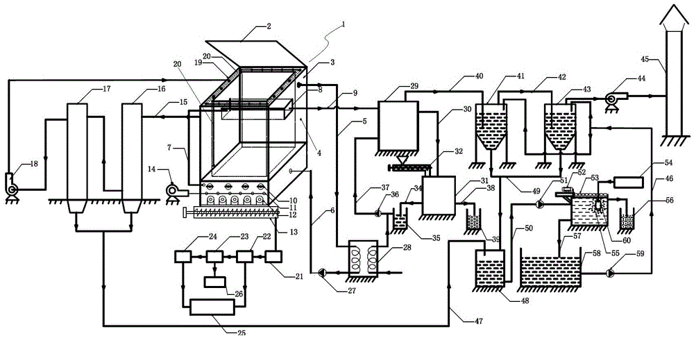
[0041] Such as figure 1 As shown, a multifunctional solid waste treatment device includes a pyrolysis gasification furnace 1, the pyrolysis gasification furnace 1 includes a furnace body 3, a flue gas drying box 8 with both ends fixed on the upper inner wall of the furnace body 3, The top of the furnace body 3 is provided with a combustible gas gas storage box 19 , and the combustible gas gas storage box 19 communicates with the bottom of the furnace body 3 through a combustible gas combustion-supporting conduit 20 .

[0042]The upper part of the body of furnace 3 is provided with a combustible gas outlet pipe 15, the combustible gas outlet pipe 15 is connected with a condensing device, and the output end of the condensing device is connected with a combustible gas storage box 19 through a pipeline. The condensing device includes a primary condenser 16 and a secondary condenser 17, and an induced draft fan 18 is provided between the secondary condenser 17 and a gas storage box...


PUM


Abstract

The invention discloses a multifunctional solid waste treatment device. The multifunctional solid waste treatment device comprises a pyrolysis gasifier. The pyrolysis gasifier comprises a gasifier body and a smoke drying box. A combustible gas storage box is arranged on the top of the gasifier body and communicated with the bottom of the gasifier body. A combustible gas delivery pipe is arranged on the upper portion of the gasifier body and connected with a condensation device, and the condensation device is connected with the combustible gas storage box. A smoke internal delivery pipe is arranged on the lower portion of the gasifier body, the smoke drying box is connected with a waste heat boiler connected with a smoke washing system, and the waste heat boiler is connected with a sludge drying device. The smoke washing system is connected with a sewage pool and a chimney, and the condensation device is connected with the sewage pool. The sewage pool is connected with a tar-water separation system capable of separating tar and water. The invention further provides a solid waste treatment method. By means of the device and the method, solid waste can be completely treated, combustion is complete, smoke is exhausted after reaching the standard, and meanwhile sludge treatment capacity is achieved.

Description

technical field [0001] The invention belongs to the field of environmental protection equipment, and in particular relates to a multifunctional solid waste treatment device and a solid waste treatment method thereof. Background technique [0002] With the acceleration of the construction of new socialist countryside in our country, the construction of beautiful villages is accelerating. are getting more and more attention. At present, the method of disposal is still dominated by landfill. Due to the lack of a large amount of capital investment and the non-standard construction of the landfill, a large amount of leachate in the landfill was released, polluting the underground (surface) water source, and seriously affecting the health of the surrounding villagers. With the financial support of the state, although some small-scale garbage incinerators and gasifiers have been built, the technology of incinerators and gasifiers is not up to standard, the treatment is not comple...

Claims


Application Information

Patent Timeline
IPC IPC(8): F23G5/027F23G5/04F23G5/44F23G5/46F23J15/04C02F11/12
CPCC02F11/12F23G5/027F23G5/04F23G5/44F23G5/46F23G2201/10F23G2201/303F23G2206/203F23J15/04F23J2217/50Y02E20/12
Inventor 刘曜王梅强王自立冯利华李水生周莉殷浪
Owner 深鹏环保工程有限公司
Learn More