
Pneumatic precise filling machine

A filling machine and air pressure technology, which is applied in the field of improvement and invention of air pressure precision filling machines, can solve the problems of difficult processing technology, large errors, leakage measurement, etc., and achieve outstanding substantive features, good economic benefits, The effect of improving productivity

Inactive Publication Date: 2016-05-04
瑞安市椰竹洗涤用品厂
View PDF7 Cites 5 Cited by
  • Summary
  • Abstract
  • Description
  • Claims
  • Application Information

AI Technical Summary

Problems solved by technology

[0002] In the prior art, the pumping type of the filling machine is easy to generate air bubbles that will affect the filling liquid, while the cylinder is used to directly drag the piston barrel, suck the filling liquid into the barrel, and then push the liquid into the filling bottle In this way, the piston barrel will pollute the filling liquid because the sealing material must be a rubber and plastic sealing ring, and the sealing ring will wear out after long-term reciprocating work, which will easily lead to leakage and make the measurement inaccurate. The method of measuring the weight of different filling liquids equal to the volume and multiplying the specific gravity makes each batch of each filling liquid have to be manually calculated, which is troublesome to operate, and the measurement is indirect weight instead of direct weight, which makes the error large. At the same time, the existing filling machine has complex mechanical structure and difficult processing technology, resulting in high cost

Method used


Image

  • Pneumatic precise filling machine
  • Pneumatic precise filling machine

Examples


Embodiment 1

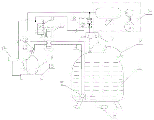
[0016] Embodiment one, see appendix figure 1 , the electric control switch includes a second solenoid valve 10 and an air control on-stop valve 11, the air control on-stop valve 11 is arranged on the upper end of the liquid riser 4, the air control on-off valve 11 communicates with the air pump 9 through the air pipe, and the second electromagnetic A valve 10 is provided on this trachea. When working, the second solenoid valve 10 controls the opening and closing of the air pipe, and realizes the on-off of the air-controlled on-off valve 11 to control the opening and closing of the upper end of the riser pipe 4, wherein the air-operated on-off valve 11 is a valve driven by a cylinder. Body, the cylinder is connected with the air pipe.

Embodiment 2

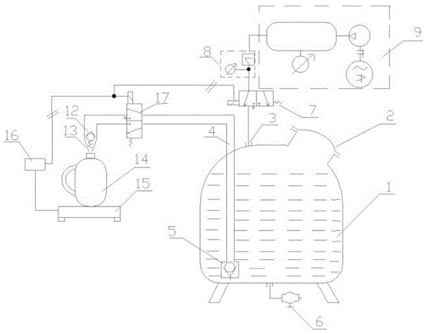
[0017] Embodiment two, see appendix figure 2 , the electronically controlled switch can also be a separate third electromagnetic valve 17 to control the opening and closing of the upper end of the riser pipe 4 .

[0018] In the present invention, preferably, a check valve 5 is provided at the lower end of the liquid riser 4 to prevent the liquid from flowing back. The filling nozzle 13 is provided with an anti-drip one-way pressure valve 12 to prevent the filling liquid from dripping onto the electronic scale 15 when the bottle is replaced, thereby affecting the next weighing measurement. The bottom of the liquid storage tank 1 is provided with a cleaning discharge port, and the discharge port is provided with a ball valve 6 switch, which facilitates the cleaning of the liquid storage tank 1 and meets the needs of the same liquid storage tank 1 for filling different liquids. The air pump 9 is a combination of frequency modulation motor air pump 9, which realizes the adjustab...


PUM


Abstract

The invention discloses a pneumatic precise filling machine. The pneumatic precise filling machine comprises a liquid storage tank, a sealing cover, electromagnetic valves and a filling nozzle. The sealing cover is arranged at an opening of the liquid storage tank. The pneumatic precise filling machine is characterized in that the filling machine further comprises a riser tube and an air pump; the lower end of the riser tube stretches into the bottom of the liquid storage tank, the filling nozzle is arranged at the upper end of the riser tube, and an electric-control switch is also arranged at the upper end of the riser tube; the air pump communicates with a connector at the upper end of the liquid storage tank through an air pipe, and a pressure reducing valve and the first electromagnetic valve are arranged on the air pipe through which the air pump communicates with the liquid storage tank; an electronic scale is arranged below the filling nozzle, the electronic scale, the electric-control switch and the first electromagnetic valve are all electrically connected with a programmable logic controller, and both the first electromagnetic valve and the electric-control switch are opened and closed through the programmable logic controller according to the weighing information of the electronic scale. The pneumatic precise filling machine is reasonable in structure; pneumatic liquid filling is adopted, so that the problem that the storage quality of liquid is affected due to the fact that bubbles are generated in the liquid filling process is solved.

Description

technical field [0001] The invention relates to an improved invention of a filling machine in the fields of liquid medicine, beverage, chemical liquid preparation, viscous colloid, etc., and in particular to an improved invention of a pneumatic precision filling machine. Background technique [0002] In the prior art, the pumping type of the filling machine is easy to generate air bubbles that will affect the filling liquid, while the cylinder is used to directly drag the piston barrel, suck the filling liquid into the barrel, and then push the liquid into the filling bottle In this way, the piston barrel will pollute the filling liquid because the sealing material must be a rubber and plastic sealing ring, and the sealing ring will wear out after long-term reciprocating work, which will easily lead to leakage and make the measurement inaccurate. The method of measuring the weight of different filling liquids equal to the volume and multiplying the specific gravity makes eac...

Claims


Application Information

Patent Timeline
Patent Type & Authority Applications(China)
IPC IPC(8): B67C3/12B67C3/28B67C3/26B67C3/24
CPCB67C3/12B67C3/24B67C3/26B67C3/28
Inventor 孙勇
Owner 瑞安市椰竹洗涤用品厂
Learn More