Servo hydraulic type bottle cap compression molding machine

A hydraulic and forming machine technology, which is applied to household components, household appliances, and other household appliances, and can solve problems such as delayed response time, low production efficiency, and bulkiness

Active Publication Date: 2016-05-04
TAIZHOU HUANGYAN YIJING PLASTIC & MOLD
View PDF10 Cites 3 Cited by
  • Summary
  • Abstract
  • Description
  • Claims
  • Application Information

AI Technical Summary

Problems solved by technology

The disadvantage is that it is troublesome to install, the coaxiality between the boards needs to be adjusted, and it is not easy to debug, especially the main shaft needs to be very thick so as not to break, the cost is high and heavy, the bearings of each board need to be replaced normally, and maintenance is inconvenient
In particular,

Method used


Image

  • Servo hydraulic type bottle cap compression molding machine
  • Servo hydraulic type bottle cap compression molding machine
  • Servo hydraulic type bottle cap compression molding machine

Examples


Embodiment Construction

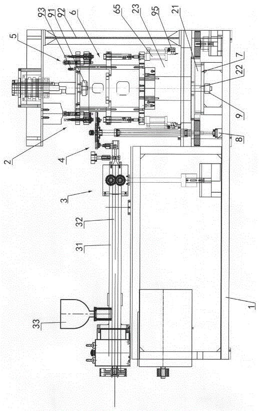
[0011] The invention relates to a servo hydraulic bottle cap compression molding machine, such as figure 1 — Figure 4 As shown, it includes a main engine assembly 2, an extrusion mechanism 3, a feeding mechanism 4, a cover mechanism 5, a mold part 6 and a transmission mechanism 7 arranged on the frame 1. The transmission mechanism is driven by a motor 8. The extrusion The discharge mechanism 3 includes a heating barrel 31 and a heating screw 32. There is a hopper 33 on the heating barrel. The head of the heating barrel is provided with a discharge port. The discharge port is matched with the feeding mechanism 4. The cover mechanism 5 and the mold part 6 is arranged on the host assembly 2, the mold part 6 includes an upper mold 61 and a lower mold 62, and the host assembly 2 includes a heavy-duty bearing 21 set in the frame 1, and a support is installed on the heavy-duty bearing 21 Body 23, connecting flange 24 and oil separator 25 are installed on the supporting body, the lo...


PUM


Abstract

A servo hydraulic type bottle cap compression molding machine comprises a main machine assembly, an extrusion mechanism, a feeding mechanism, a cap discharging mechanism, a die part and a transmission mechanism, all of which are arranged on a rack. The transmission mechanism is driven by a motor. The main machine assembly comprises a heavy load bearing arranged in the rack. The lower portion of the heavy load bearing is connected with a main shaft. The main shaft is connected with the transmission mechanism and provided with a precise electric conduction slip ring. One end of the precise electric conduction slip ring is connected with a rotary encoder connected with a human-computer interface. The human-computer interface is connected with an electric control valve connected with a die stripping and air blowing valve. A proportional servo hydraulic valve is arranged below a gland oil cylinder and provided with a pressure sensor. The pressure sensor is connected with a displacement induction piece connected with a displacement sensor. The displacement sensor is connected with the other end of the precise electric conduction slip ring. According to the scheme, the electric conduction slip ring is adopted for electric conduction, air blowing and die stripping are controlled through a servo hydraulic gland and the electric control valve, control is accurate, and the speed and the production efficiency are high.

Description

technical field [0001] The invention relates to a servo hydraulic bottle cap compression molding machine, which is mainly used for producing bottle caps of mineral water bottles, beverage bottles and oil bottles, etc., and belongs to the field of plastic machinery. Background technique [0002] At present, bottle caps such as mineral water bottles, beverage bottles and oil bottles are mainly molded by bottle cap molding machines. Install the upper mold and cover removal mechanism on the upper part, install the middle plate on the middle part of the integral rotating seat, install the lower mold on the middle plate, install the lower plate on the lower part of the integral rotating seat, install the oil cylinder ejection molding mechanism on the lower plate, and install the oil separator under the lower plate The main plate and the main shaft run through the upper plate, the integral rotating seat, the middle plate, the lower plate and the oil separator, and are connected to ...

Claims


Application Information

Patent Timeline
IPC IPC(8): B29C69/02B29C47/00B29C43/04B29C43/34B29C43/58B29L31/56
CPCB29C43/04B29C43/34B29C43/58B29C48/0011B29C2043/3405B29C2043/5833B29L2031/56
Inventor 黄海燕
Owner TAIZHOU HUANGYAN YIJING PLASTIC & MOLD
Why Eureka
Try Eureka