Special-shaped lens machining method based on computer aided manufacturing (CAM)

A special-shaped lens and processing method technology, applied in metal processing equipment, manufacturing tools, grinding machines, etc., can solve the problems of difficult processing of special-shaped lenses, low efficiency, low precision, etc., achieve good application prospects, convenient operation, and reduce processing waste rate effect

Active Publication Date: 2016-05-04
LUOYANG INST OF ELECTRO OPTICAL EQUIP OF AVIC
View PDF7 Cites 7 Cited by
  • Summary
  • Abstract
  • Description
  • Claims
  • Application Information

AI Technical Summary

Problems solved by technology

[0005] The purpose of the present invention is to provide a CAM-based special-shaped lens processing method to solve the problems of existing special-shaped lens processing difficulties, low precision and low efficiency

Method used


Image

  • Special-shaped lens machining method based on computer aided manufacturing (CAM)
  • Special-shaped lens machining method based on computer aided manufacturing (CAM)
  • Special-shaped lens machining method based on computer aided manufacturing (CAM)

Examples


Embodiment 1

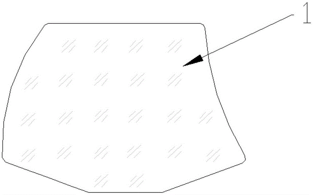
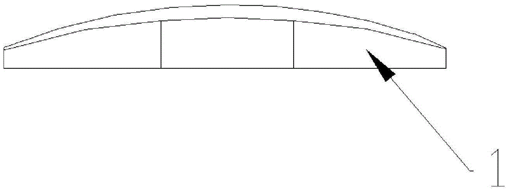
[0035] The shape of the special-shaped lens to be processed in this embodiment is as follows: figure 1 , 2 As shown, the process requirements are (length unit is mm):

[0036] size: 27.2±0.1, 27.2±0.1;

[0037] Arc radius: R52.645±0.1, R38.355±0.1;

[0038] Round: R1;

[0039] Angle: 160°±2', 160°±2';

[0040] Roughness: Ra3.2.

[0041] The CAM-based special-shaped lens processing method of the present embodiment comprises the following steps:

[0042] 1) UG7.5 establishes a rotationally symmetrical mirror blank model (circle) of φ50.6mm, one side is a plane (the plane is the mounting surface for fitting with the tooling), the other side is a convex surface, and the radius of the curved surface is 66.385mm; in accordance with figure 1 , 2 And process requirements, cut into the target special-shaped lens model;

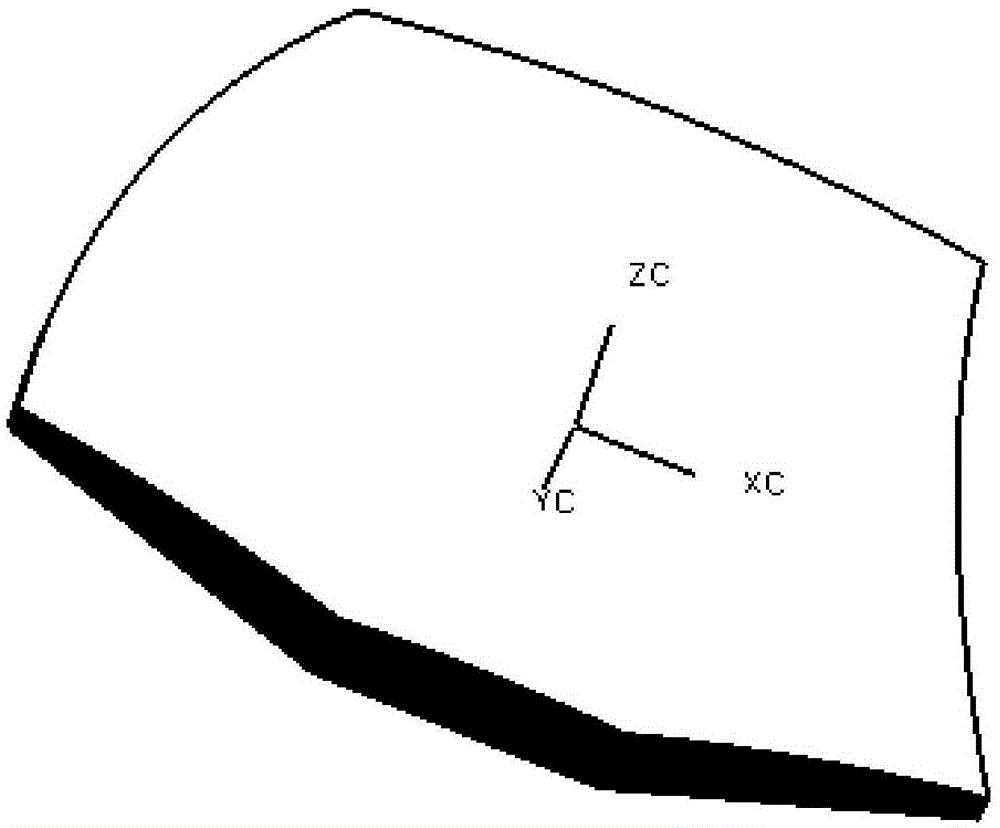
[0043] 2) Use the right-handed coordinate system, such as image 3 As shown, find the rotation axis of the circular mirror blank model before cutting, and ...


PUM


Abstract

The invention discloses a special-shaped lens machining method based on computer aided manufacturing (CAM). The special-shaped lens machining method based on CAM comprises the steps that a rotary symmetrical lens blank model is established, and the rotary symmetrical lens blank model is cut into a target special-shaped lens model; a right-handed coordinate system is adopted, the origin of coordinates is determined, the distance d between the zero point of the Z coordinate and an installation surface, used for being matched with a tool, on a lens blank meets the equation of d=delta Z-H, and H is the height of the tool; a cutter path is generated through CAM; post-processing is conducted, an NC program code is generated, and a tool axis and a cooling liquid control code are converted, so that a machining program is obtained; the lens blank is installed on the tool, and the outer circle of the lens blank is polished, so that the tool provided with the lens blank is obtained; and the outline of the lens blank is milled and ground according to the machining program till the boundary dimension and angle of the lens blank meet the design requirements. By the adoption of the special-shaped lens machining method based on CAM, machine-forming of the outline of a special-shaped lens is achieved, and the defects that the precision of manual milling and grinding is poor, and the efficiency of manual milling and grinding is low are overcome; the limitation that a machine tool is provided with modular software is broken through, and the machining efficiency and machining precision are improved; the rejection rate of machining is decreased; the technique is simple, operation is convenient, and the special-shaped lens machining method has good application prospects.

Description

technical field [0001] The invention belongs to the technical field of special-shaped lenses, and in particular relates to a CAM-based processing method for special-shaped lenses. Background technique [0002] A spherical lens is one that has a constant curvature from the center to the edge of the lens, while an aspherical lens has a curvature that changes continuously from the center to the edge. The radius of curvature of the aspheric lens changes with the central axis to improve optical quality, reduce optical components, and reduce design costs; this lens has a wider radius of curvature, which can maintain good aberration correction to obtain the required performance . Since the aspheric lens has been designed with correction factors in mind, one piece can replace several spherical lenses to compensate for aberrations, which can significantly simplify the optical design. Compared with spherical lenses, aspherical lenses have excellent sharpness and higher resolution, a...

Claims


Application Information

Patent Timeline
Patent Type & Authority Applications(China)
IPC IPC(8): B24B13/00
CPCB24B13/00
Inventor 袁兆峰石雷王彦伟孙红晓
Owner LUOYANG INST OF ELECTRO OPTICAL EQUIP OF AVIC
Why Eureka
Try Eureka