
Engine device to be mounted on working machine

A technology for working machines and engines, which is applied to the field of engine devices for working machines, can solve the problems of inability to simplify the supporting structure of an exhaust gas purification box, and achieve the effects of simplifying the supporting structure, low cost, and improving seismic strength

Inactive Publication Date: 2016-04-20
YANMAR CO LTD
View PDF5 Cites 3 Cited by
  • Summary
  • Abstract
  • Description
  • Claims
  • Application Information

AI Technical Summary

Problems solved by technology

[0007] The above-mentioned prior art has the problem that, in a structure provided with an exhaust gas purification box for removing particulate matter (smoke, fine particles) contained in exhaust gas and an exhaust gas purification box for removing nitrogen oxides (NOx) contained in exhaust gas, In the engine room, it is necessary to ensure the installation space of the engine and multiple or single exhaust gas purification boxes. The volume of the engine room or the volume of the exhaust gas purification device (exhaust gas purification box) is mutually limited, and it is impossible to combine the volume of multiple or single exhaust gas purification boxes. Simplification of supporting structure, etc.

Method used


Image

  • Engine device to be mounted on working machine
  • Engine device to be mounted on working machine
  • Engine device to be mounted on working machine

Examples


Embodiment Construction

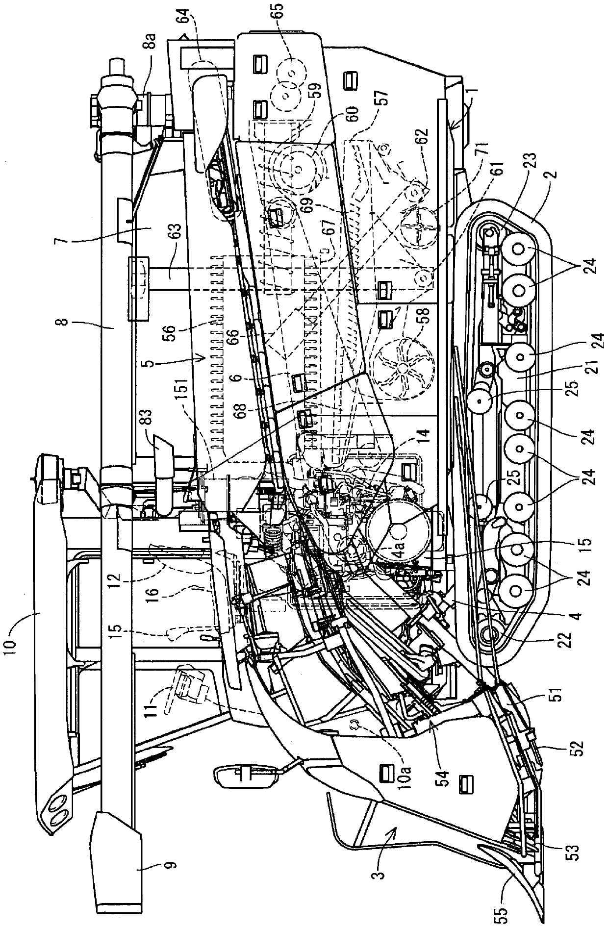
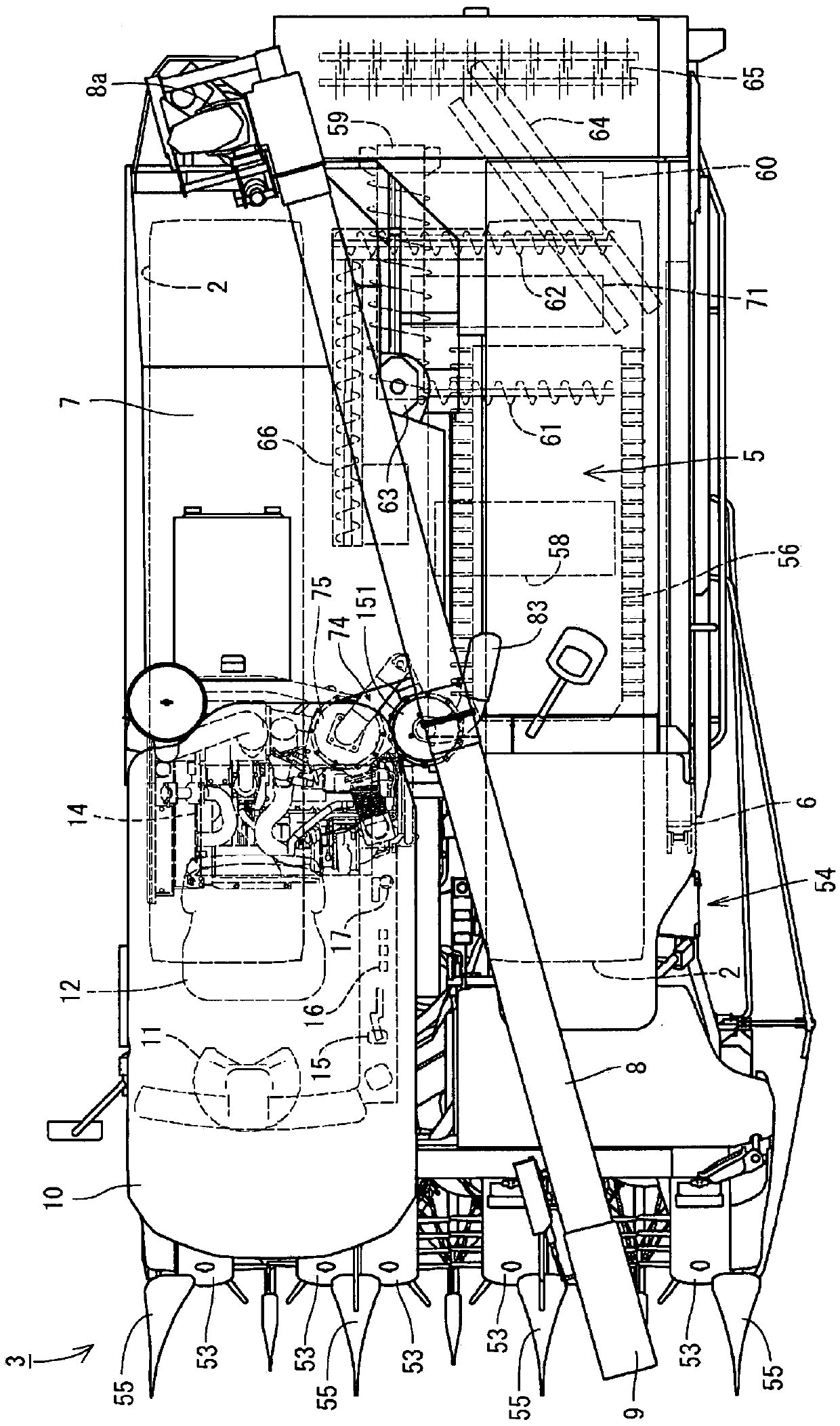
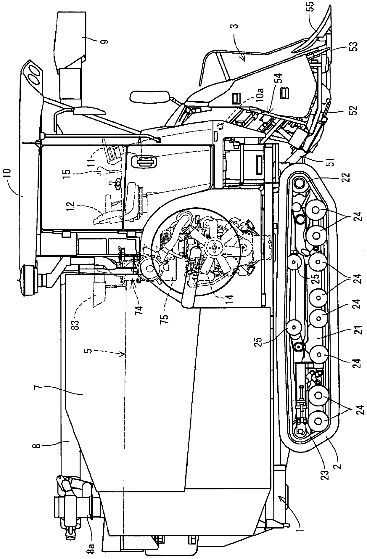
[0045] Hereinafter, a first embodiment embodying the present invention will be described based on the drawings. Refer to as the first embodiment Figure 1 to Figure 3 (Of the second embodiment Figure 9 to Figure 11 ), the overall structure of a combine as a working machine equipped with a diesel engine will be described. In addition, in the following description, the left side when facing the forward direction of the traveling body 1 is simply referred to as the left side, and similarly, the right side when facing the forward direction is simply referred to as the right side. Such as Figure 1 to Figure 3 ( Figure 9 to Figure 11 As shown in ), there is a traveling body 1 supported by a pair of left and right traveling crawlers 2 as a traveling portion. The harvesting device 3 for harvesting six stalks for harvesting and taking in the straw is assembled on the front part of the traveling machine body 1 through a single-acting hydraulic cylinder 4 for lifting in a manner capabl...


PUM


Abstract

The present invention addresses the problem of providing an engine device to be mounted on a working machine, said engine device being constructed such that a support structure for multiple or a single exhaust gas purification case (75, 151) and the like can be simplified, and the multiple or single exhaust gas purification case (75, 151) can be easily attached to a working vehicle such as an agricultural machine or a construction machine. In this engine device to be mounted on a working machine, multiple or a single exhaust gas purification case (75, 151) for treating the exhaust gas of a diesel engine (14) is provided, and an exhaust gas inlet port of the exhaust gas purification case (75, 151) is connected to an exhaust pipe (119) of the diesel engine (14). The engine device is constructed such that an engine compartment frame (91) is provided on a traveling machine body (1), an engine compartment (97) is formed by the engine compartment frame (91), and the diesel engine (14) is installed inside the engine compartment (97), and is equipped with an exhaust gas purification unit frame (114) that secures the multiple or single exhaust gas purification case (75, 151) as one unit, said exhaust gas purification unit frame (114) being detachably mounted either on the diesel engine (14) or on the engine compartment frame (91).

Description

Technical field [0001] The present invention relates to working vehicles such as agricultural machinery (combines, tractors) or construction machinery (bulldozers, hydraulic excavators, loaders) equipped with engines, and more specifically, to operations with exhaust gas purification devices (exhaust gas purification boxes) An engine device for machine mounting that removes particulate matter (soot, particulate) contained in exhaust gas or nitrogen oxides (NOx) contained in exhaust gas. Background technique [0002] Conventionally, a combine harvesting mechanism as a working machine has a traveling body equipped with an engine, a pair of left and right traveling crawlers are installed on the traveling body, and the pair of left and right traveling crawlers are driven and controlled to move in farmland or the like. In addition, the combined harvesting mechanism is: the roots of the uncut straw planted in the farmland are cut by a cutter device, the straw is conveyed to the threshi...

Claims


Application Information

Patent Timeline
IPC IPC(8): F01N3/28F01N3/02A01D41/12B60K13/04
CPCB60K13/04B60Y2200/222F01N13/1822F01N13/1855F01N2590/08F01N13/009
Inventor 小西义史
Owner YANMAR CO LTD
Learn More