Unit with power circuit mounted therein, and motor drive apparatus

A technology for power supply circuits and motors, applied in circuit devices, circuit thermal devices, printed circuit components, etc., can solve the problems of noise superposition, detection errors, etc., and achieve the effect of preventing false detection and increasing the heat dissipation area.

Active Publication Date: 2012-10-31
DAIKIN IND LTD
View PDF2 Cites 0 Cited by
  • Summary
  • Abstract
  • Description
  • Claims
  • Application Information

AI Technical Summary

Problems solved by technology

For this reason, in the detection circuit installed near the heat sink, due to the influence of electromagnetic waves from the heat sink, noise may be superimposed on the detection signal, causing detection errors.

Method used


Image

  • Unit with power circuit mounted therein, and motor drive apparatus
  • Unit with power circuit mounted therein, and motor drive apparatus

Examples


other Embodiment approach

[0059] The above embodiments may also take the following configurations.

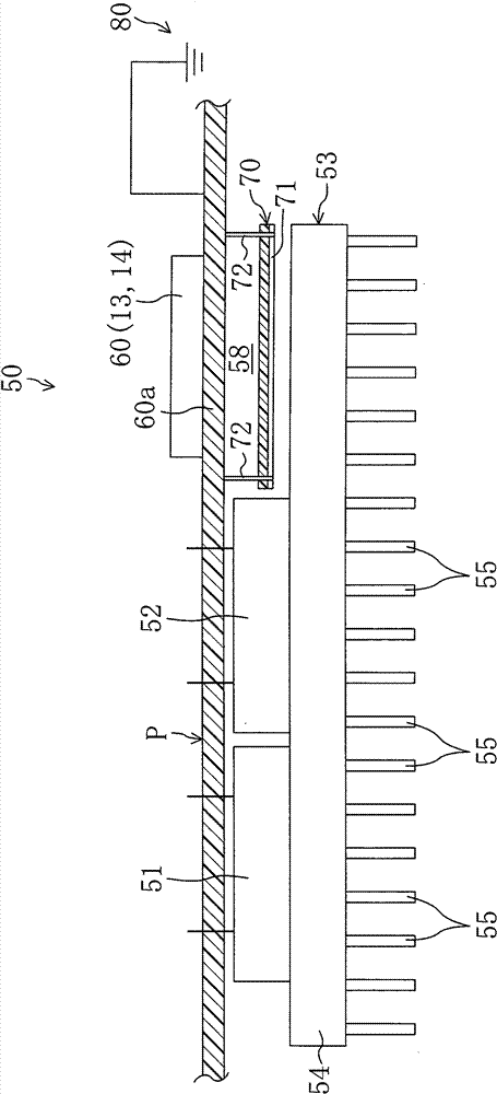
[0060] In the above-described embodiment, the detection circuit 60 and the heat sink 53 are disposed opposite to each other with the printed substrate P sandwiched therebetween, but it may also be arranged such that the detection circuit 60 is moved so that the detection circuit 60 and the heat sink 53 are aligned in the thickness direction of the substrate. do not overlap each other. In this case, noise may be superimposed on the detection circuit 60 due to the influence of electromagnetic waves generated from the heat sink 53 , but the electromagnetic shield 70 can reduce the influence of electromagnetic waves.

[0061] In addition, in the above-described embodiment, the electromagnetic shield 70 is connected to the ground portion on the printed circuit board P side, but a ground wire may be directly connected to the electromagnetic shield 70 to make the electromagnetic shield 70 a ground potential. ...


PUM


Abstract

A first power module, a second power module and a detecting circuit are mounted on a printed board. On the surface of each power module, a heat sink is attached. In a space between the mounting portion of the detecting circuit on the printed board and a base section of the heat sink, an electromagnetic wave blocking material is arranged for blocking electromagnetic waves traveling from the heat sink side toward the detecting circuit side.

Description

technical field [0001] The present invention relates to a component (unit) installed with a power circuit (power circuit), in particular to a method for reducing noise caused by switching action in a power module. A power module is mounted on the substrate of the power circuit-mounted module. Background technique [0002] Heretofore, a power supply circuit-mounted package having a power module has been applied to a driving device of a motor of a compressor or the like. [0003] In Patent Document 1, such a power supply circuit-mounted package is disclosed. In an assembly mounted with a power supply circuit, a power module having a switching element is mounted on a substrate. A heat sink for cooling the power module is provided in the package on which the power supply circuit is mounted. [0004] Also, Patent Document 2 discloses a power circuit-mounted module in which a heat sink is mounted on the surface of a power module. The heat generated in the switching element is ...

Claims


Application Information

Patent Timeline
Patent Type & Authority Patents(China)
IPC IPC(8): H05K9/00H05K1/02H05K7/20H02M7/48
CPCH02M5/4585H05K2201/10515H02M7/003H01L2924/0002H05K9/0022H05K2201/10371H02M1/44H05K1/18H05K2201/10151H05K2201/10545H05K7/20909H05K1/0203H05K1/0218H05K2201/1056H01L2924/00
Inventor 石关晋一佐藤俊彰
Owner DAIKIN IND LTD
Why Eureka
Try Eureka