
combine harvester

A technology of combine harvesters and harvesting devices, which is applied in the directions of harvesters, cutters, agricultural machinery and implements to achieve the effect of simplifying the support structure

Inactive Publication Date: 2016-08-17
YANMAR CO LTD
View PDF7 Cites 0 Cited by
  • Summary
  • Abstract
  • Description
  • Claims
  • Application Information

AI Technical Summary

Problems solved by technology

For example, there is a problem that the second cutter frame cannot be easily incorporated into the traveling body structure that is not equipped with the second cutter blade through post-installation processing.
For example, there is a problem that the driving structure of the second cutting blade cannot be easily incorporated into the driving structure of the harvesting device without the second cutting blade through post-installation processing.

Method used


Image

  • combine harvester
  • combine harvester
  • combine harvester

Examples


Embodiment Construction

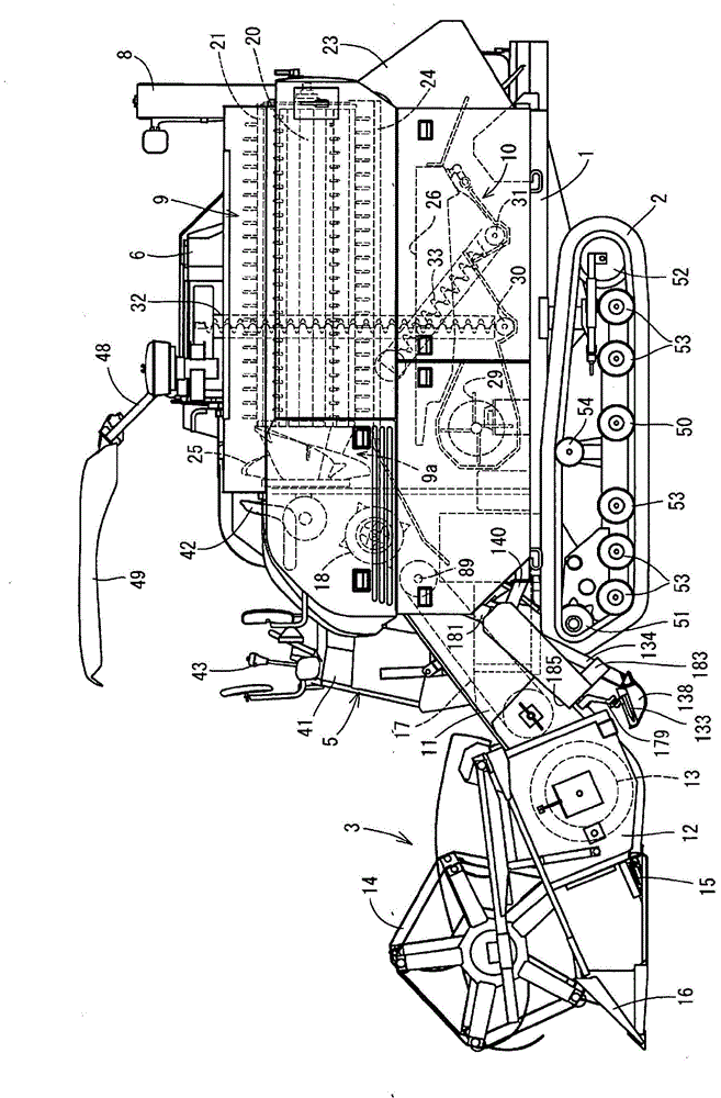
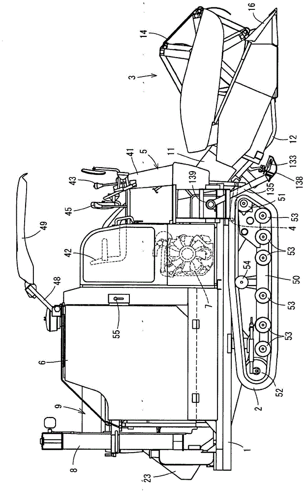
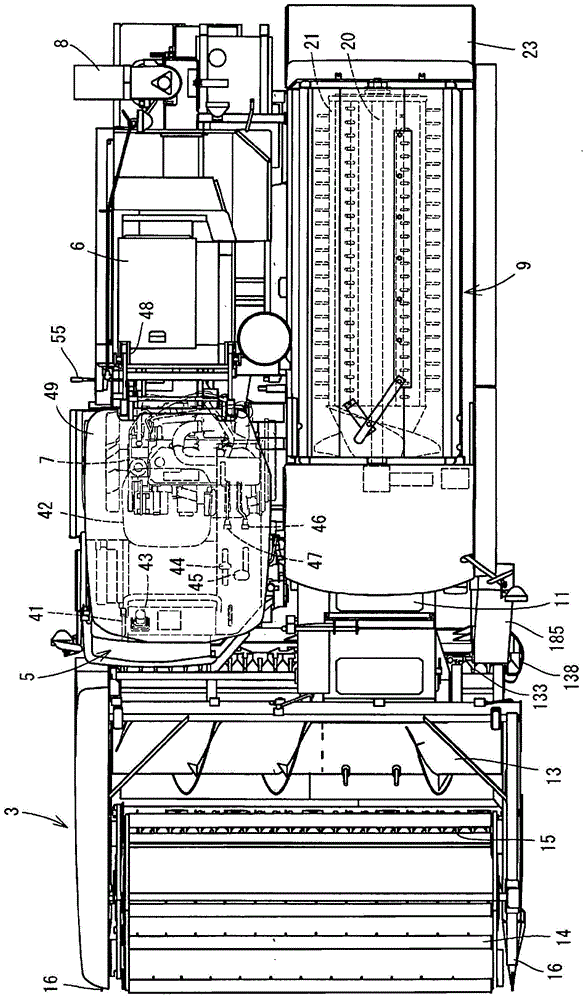
[0048] Below, according to the accompanying drawing ( Figure 1 to Figure 5 ) to describe an embodiment that actualized the present application. figure 1 is the left side view of the combine harvester, figure 2 is its right side view, image 3 is its top view, Figure 4 is its left stereogram, Figure 5 is its rear view. First, see Figure 1 to Figure 5 , the schematic structure of the combine harvester will be described. In addition, in the following description, toward the advancing direction of the traveling body 1, the left side is simply called the left side, and similarly, toward the advancing direction, the right side is simply called the right side.

[0049] Such as Figure 1 to Figure 5 As shown, the common type combine harvester in embodiment is equipped with the traveling body 1 supported by the left and right pair of crawler belts 2 made from the track roller (Gomkrolla) which is a traveling part. The front portion of traveling body 1 is equipped with the ...


PUM


Abstract

The present invention provides a combine for which a constitution in which a forward and reverse switching case (121) and a second cutting blade drive mechanism (171) are attachable and detachable can be achieved and for which a support structure for a second cutting blade (133) can be manufactured simply or inexpensively. This combine is provided with: a reaper (3) to which a first cutting blade (15) is attached; a thresher (9) that has a processing cavity (21); a drive machine (1) in which an engine (7) and an operator's seat (42) are provided; and the second cutting blade (133) which cuts stalks left from the first cutting blade (15). The second cutting blade (133) adjusts the height of stalks cut in a field. The forward and reverse switching case (121) is provided to input the rotational drive force of the engine (7) to the reaper (3). The second cutting blade drive mechanism (171) is provided to transfer the drive force from the forward and reverse switching case (121) to the second cutting blade (133).

Description

technical field [0001] This application relates to the combine harvester equipped with the harvesting apparatus of the uncut stems which harvest a field, and the threshing apparatus which threshes the grain of a harvested grain stem. Background technique [0002] Conventionally, the following technologies are known, that is, a traveling machine body having a traveling portion and a driver's seat, a reaping device having a first blade, a threshing device having a threshing drum, and a device for supplying harvested grain stalks from the reaping device to the threshing device are known. The feed chamber, the engine that drives each part, and the grain sorting mechanism that sorts the threshed products of the threshing device are equipped with a mechanism that continuously harvests the uncut grain stalks of the field, performs threshing, and cuts off the remaining stalks of the first cutter blade The 2nd cutting blade adjusts the remaining stem height of the field by the aforem...

Claims


Application Information

Patent Timeline
Patent Type & Authority Patents(China)
IPC IPC(8): A01D34/30A01D34/13
CPCA01D34/30A01D34/8355A01D41/142
Inventor 佐藤孝康大原研二
Owner YANMAR CO LTD
Learn More