
Control method and device of microwave oven circuit and microwave oven

A control method and technology of a control device, which are applied in the field of microwave ovens, can solve the problems of high maintenance rate of the rectifier bridge stack 1', easy damage to the rectifier bridge stack, damage to the rectifier bridge stack, etc., so as to improve the service life, prolong the service life, The effect of improving reliability

Active Publication Date: 2016-04-20
GUANGDONG MIDEA KITCHEN APPLIANCES MFG CO LTD +1
View PDF3 Cites 7 Cited by
  • Summary
  • Abstract
  • Description
  • Claims
  • Application Information

AI Technical Summary

Problems solved by technology

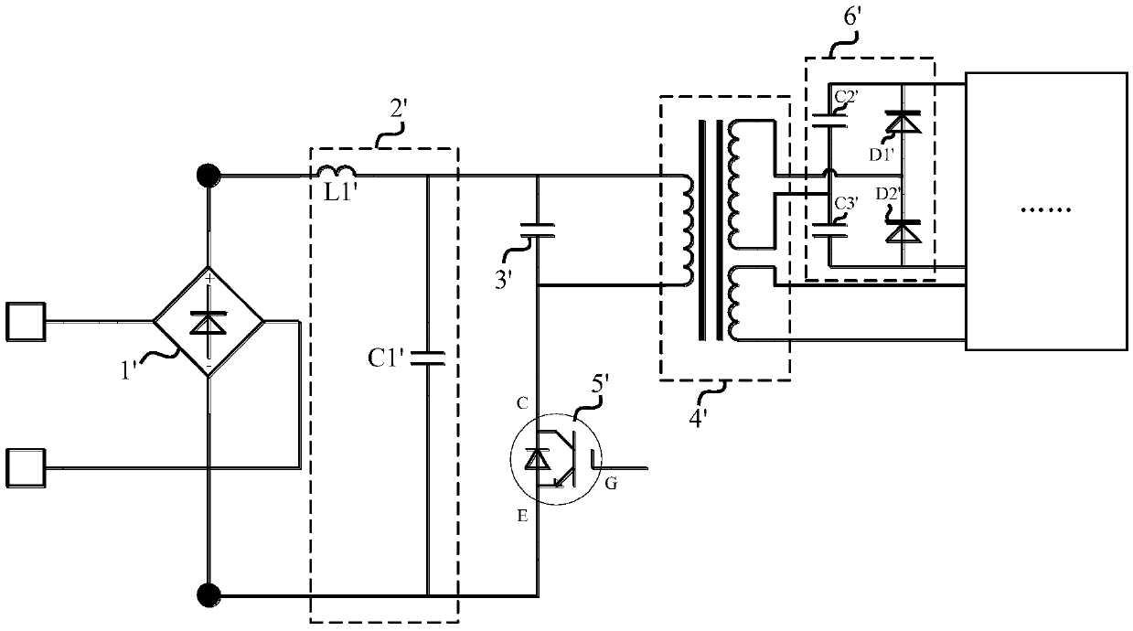
Assuming that the mains power is 220V AC, if the mains signal is at a peak value of 310V, and the voltage across the capacitor C2' is 0 when the microwave relay is turned on, then the voltage across the capacitor C2' cannot change suddenly at the moment the microwave relay is turned on, and the peak value of the mains power 310V is directly applied to the inductor L1'. Due to the characteristics of the inductor (that is, the current cannot change suddenly), a large reverse voltage will be generated to prevent the current from increasing. Therefore, at the front end, that is, the port of the rectifier bridge stack 1', a large Large voltage, up to 1000V, easily damages the rectifier bridge stack 1'
This theoretical analysis is also consistent with the feedback data from the market, that is, the maintenance rate of bridge rectifier 1' remains high
[0008] At the same time, another high maintenance rate is IGBT5', because the G pole voltage of the IGBT cannot exceed 25V, but under the existing control mode, when the microwave relay is turned on, the G pole of the IGBT occasionally has a voltage above 33V
[0009] Therefore, how to reduce the voltage at both ends of the rectifier bridge stack when the inverter is turned on, to avoid damage to the rectifier bridge stack due to excessive voltage at both ends of the rectifier bridge stack, and to avoid damage to the G pole of the IGBT due to excessive voltage has become an urgent problem to be solved. technical problem

Method used


Image

  • Control method and device of microwave oven circuit and microwave oven
  • Control method and device of microwave oven circuit and microwave oven
  • Control method and device of microwave oven circuit and microwave oven

Examples


Embodiment Construction

[0057] In order to understand the above-mentioned purpose, features and advantages of the present invention more clearly, the present invention will be further described in detail below in conjunction with the accompanying drawings and specific embodiments. It should be noted that, in the case of no conflict, the embodiments of the present application and the features in the embodiments can be combined with each other.

[0058] In the following description, many specific details are set forth in order to fully understand the present invention. However, the present invention can also be implemented in other ways different from those described here. Therefore, the protection scope of the present invention is not limited by the specific details disclosed below. EXAMPLE LIMITATIONS.

[0059] Figure 5 A schematic structural diagram of a microwave oven circuit according to an embodiment of the present invention is shown.

[0060] Such as Figure 5 As shown, the microwave oven ci...


PUM


Abstract

The invention provides a control method and device of a microwave oven circuit and a microwave oven. The microwave oven circuit comprises a magnetron and an inverter circuit driving the magnetron to operate. The control method comprises steps of: detecting the zero-crossing point (ZCP) of a commercial power signal powering the microwave oven circuit when the inverter circuit is required to be started; enabling the inverter circuit to be powered up when it is detect that the commercial power signal reaches the ZCP; inputting a first power signal with a frequency lower than a target frequency into the inverter circuit when the powered time length of the inverter circuit reaches a first preset time length; detecting the current of the magnetron; and inputting a second power signal with a frequency equal to the target frequency into the inverter circuit when the current of the magnetron reaches a preset current value. The control method is capable of decreasing the voltage on both ends of a bridge rectistack and preventing the bridge rectistack from being damaged by overhigh voltage on both ends of the bridge rectistack.

Description

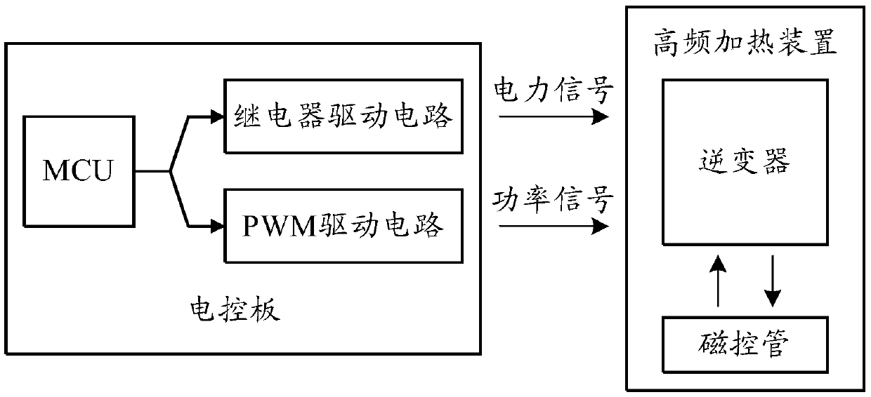
technical field [0001] The invention relates to the technical field of microwave ovens, in particular to a method for controlling microwave oven circuits, a control device for microwave oven circuits, and a microwave oven. Background technique [0002] Compared with the transformer power supply, the inverter in the microwave oven circuit has the advantages of lightness, high power factor, continuously adjustable power, etc., and has been widely favored by users. With the extensive use of inverters, the repair rate in the market has generally increased. Judging from the repair data, IGBT (Insulated Gate Bipolar Transistor, Insulated Gate Bipolar Transistor) and rectifier bridge stacks are mostly damaged. The current control method has received severe challenges. [0003] Such as figure 1 As shown, the existing frequency conversion microwave oven control system includes an electric control board and a high frequency heating device. Among them, the electric control board inc...

Claims


Application Information

Patent Timeline
Patent Type & Authority Applications(China)
IPC IPC(8): H05B6/68
CPCH05B6/68Y02B40/00
Inventor 林跃跃周小金
Owner GUANGDONG MIDEA KITCHEN APPLIANCES MFG CO LTD
Learn More