Earth fault detection device for direct current system
A DC system and grounding fault technology, applied in the direction of fault location, fault detection according to conductor type, etc., can solve problems such as power system accidents, relay protection device misoperation, etc.
- Summary
- Abstract
- Description
- Claims
- Application Information
AI Technical Summary
Problems solved by technology
Method used
Image
Examples
Embodiment 1
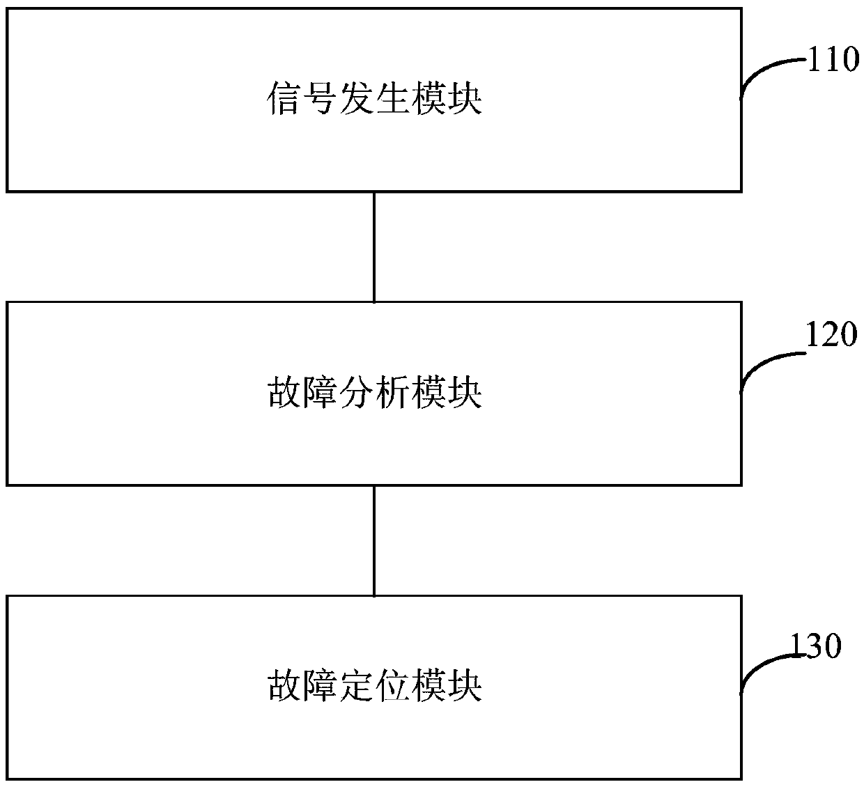
[0028] figure 1 A schematic structural diagram of a DC system ground fault detection device provided in Embodiment 1 of the present invention, the device specifically includes:
[0029] Signal generation module 110, fault analysis module 120 and fault location module 130;
[0030] Among them, the signal generation module 110 is used to set the working mode of the fault analysis module, and generate a current signal with a set frequency and amplitude matching the working mode, and inject the current signal into the DC system, firstly to Inject the current signal into the positive-to-ground of the DC system, then stop the positive-to-ground current signal after a period of time, and start injecting the current signal into the negative-to-ground of the DC system, in order to make the positive or negative voltage of the DC system The ground changes, and the frequency and amplitude of the current signal can be set arbitrarily as required.
[0031] The fault analysis module 120 is...
Embodiment 2
[0035] figure 2 A schematic diagram of the structure of a DC system ground fault detection device provided in Embodiment 2 of the present invention. On the basis of Embodiment 1, this embodiment optimizes the fault analysis module. The advantage of such optimization is that it can accurately detect the DC system Is there a ground fault. Described device specifically comprises:
[0036] The signal generation module 210 is used to set the working mode of the fault analysis module, and generate a current signal with a set frequency and amplitude matching the working mode, and inject the current signal into the DC system, and the fault analysis module 220, used to sample the changing voltage on the bus of the DC system when the positive voltage or negative voltage of the DC system changes to the ground, calculate the resistance value and distributed capacitance value of the DC system to the ground according to the sampled voltage, and calculate The above resistance value judges...
Embodiment 3
[0061] Figure 6 A schematic diagram of the structure of a DC system ground fault detection device provided by Embodiment 3 of the present invention. On the basis of the above embodiments, this embodiment optimizes the fault location module. The advantage of such optimization is that the DC system can be accurately detected. Is there a ground fault. Described device specifically comprises:
[0062] A signal generation module 310, configured to generate a current signal with a set frequency and amplitude, and inject the current signal into the DC system;
[0063] The fault analysis module 320 is configured to sample the changing voltage on the bus of the DC system when the positive or negative voltage of the DC system changes to the ground, calculate the resistance value of the DC system to ground according to the sampled voltage, and calculate the resistance value of the DC system to ground according to the resistance judge whether there is a ground fault in the DC system, a...
PUM
 Abstract
Description
Claims
Application Information
 - R&D
- Intellectual Property
- Life Sciences
- Materials
- Tech Scout
- Unparalleled Data Quality
- Higher Quality Content
- 60% Fewer Hallucinations
Browse by: Latest US Patents, China's latest patents, Technical Efficacy Thesaurus, Application Domain, Technology Topic, Popular Technical Reports.
© 2025 PatSnap. All rights reserved.Legal|Privacy policy|Modern Slavery Act Transparency Statement|Sitemap|About US| Contact US: help@patsnap.com


