Material pneumatic conveying system driven by multiple piston sheaths
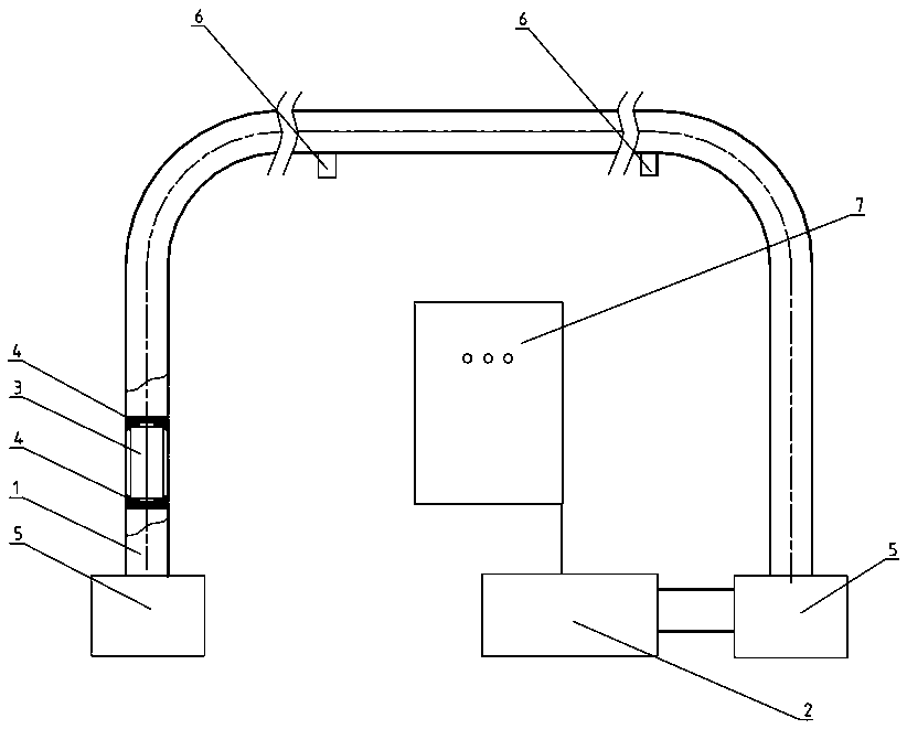
A pneumatic conveying, multi-piston technology, used in conveyors, conveying bulk materials, transportation and packaging, etc., can solve the problems of high matching of sample bottles and pipelines, sample bottle damage, and high use costs, and achieve pneumatic conveying. Variety, the effect of reducing the cost of use and reducing the maintenance cost
- Summary
- Abstract
- Description
- Claims
- Application Information
AI Technical Summary
Problems solved by technology
Method used
Image
Examples
specific Embodiment 1
[0049] Specific embodiment 1: as Figure 4 As shown, the fixed part 41 includes a protective chamber 44 that is recessed on the piston sheath 4, and the two ends of the object to be conveyed 3 are respectively carried in the protective chambers 44 of the two front and rear piston sheaths 4 so that the object to be conveyed 3 does not come into contact with the protective chamber 44. When the transmission pipeline unit 1 contacts, the opening end of the protective chamber 44 is provided with a matching guide part 45. When the piston sheath 4 pushes the object 3 to be conveyed, the guide part 45 first contacts the object 3 to be conveyed and will push the object 3 to be conveyed under the action of the thrust. The object 3 is introduced into the protection chamber 44.
[0050] Through such setting, it has the following advantages: First, because the object to be conveyed 3 is carried on the protection chamber 44 and does not contact the transmission pipeline unit 1, the front an...
specific Embodiment 2
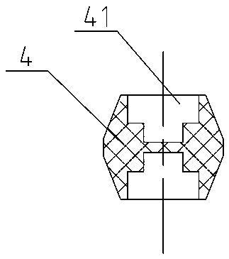
[0054] Specific embodiment 2: as image 3 and Figure 5 As shown, in this preferred embodiment, the axial ends of the piston sheath 4 are symmetrically tapered, so that the overall shape of the piston sheath 4 is a drum shape with thin ends and a thick middle, so that when the piston sheath 4 is stationary Contact with the transfer pipe unit 1 is maintained only through the axial middle. Through such a special scientific design, first, the contact surface between the piston sheath 4 and the transmission pipeline unit 1 is small, reducing the friction between the piston sheath 4 and the transmission pipeline, and the transmission resistance is small; second, this special structure makes the piston sheath 4 4. During the high-speed pneumatic conveying in the conveying pipe unit 1, it can flexibly adapt to the direction of the pipe, and effectively prevent the piston sheath 4 from turning over and being stuck.
specific Embodiment 3
[0055] Specific embodiment 3: as Figure 6 As shown, in a preferred embodiment, the outer peripheral wall of the piston sheath 4 is provided with a plurality of ribs 42 arranged along the axial direction of the piston sheath 4 . In this embodiment, a plurality of raised ribs 42 are evenly arranged on the outer peripheral wall of the piston sheath 4, and the ribs 42 are in contact with the pipeline inner wall of the transmission pipeline unit 1, so that the piston sheath 4 is in contact with the transmission pipeline unit 1 The surface is small, reducing the friction between the piston sheath 4 and the transmission pipeline, and the transmission resistance is small.
PUM
 Abstract
Description
Claims
Application Information
 - R&D
- Intellectual Property
- Life Sciences
- Materials
- Tech Scout
- Unparalleled Data Quality
- Higher Quality Content
- 60% Fewer Hallucinations
Browse by: Latest US Patents, China's latest patents, Technical Efficacy Thesaurus, Application Domain, Technology Topic, Popular Technical Reports.
© 2025 PatSnap. All rights reserved.Legal|Privacy policy|Modern Slavery Act Transparency Statement|Sitemap|About US| Contact US: help@patsnap.com


