
Milling cutter grinding fixture

A technology for grinding jigs and blades, which is applied in the field of workpiece clamping, can solve problems such as difficulty in angle adjustment, and achieve the effect of convenient sequential grinding

Inactive Publication Date: 2016-04-20
安徽池州项赛机械制造有限公司
View PDF8 Cites 1 Cited by
  • Summary
  • Abstract
  • Description
  • Claims
  • Application Information

AI Technical Summary

Problems solved by technology

[0003] The purpose of the present invention is to overcome the defect that the angle adjustment is difficult when grinding each cutter face of the three-sided milling cutter in the prior art, and a milling cutter sharpening fixture is designed, and the angle of the milling cutter can be adjusted arbitrarily

Method used


Image

  • Milling cutter grinding fixture

Examples


Embodiment Construction

[0017] In order to make the technical means, creative features, goals and effects achieved by the present invention easy to understand, the present invention will be further described below in conjunction with specific illustrations.

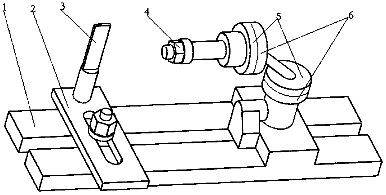
[0018] A milling cutter sharpening fixture, comprising a base 1, a slide plate 2, a positioning piece 3, a fastening nut 4, an adjustment plate 5, and a fixed plate 6, a longitudinal groove is arranged in the middle of the base 1, and the slide plate 2 can move longitudinally along the groove, Adjust the position of the slide plate 2. There is a transverse groove in the middle of the slide plate 2. When the slide plate 2 moves to a certain position in the transverse direction, it is fixed on the base 1 with nuts. Since the positioning piece 3 is embedded in the column of the slide plate 2, the slide plate 2. The transverse groove in the middle is used to adjust the position of the positioning piece 3. The positioning piece 3 is a thin metal sheet...


PUM


Abstract

The invention discloses a milling cutter grinding fixture and belongs to the technical field of workpiece clamping. The milling cutter grinding fixture comprises a base, a sliding plate, a locating sheet, a fastening nut, adjusting disks and fixed disks, wherein the sliding plate is fixed to the base by a nut; a longitudinal groove is formed in the middle of the base; the sliding plate can make longitudinal motion along the longitudinal groove, and the position of the sliding plate is adjusted; the locating sheet which is a thin metal sheet is inserted into an upright column of the base, and has good elasticity; when a milling cutter rotates clockwise, the milling cutter can rotate smoothly due to the elasticity of the locating sheet; when the milling cutter rotates anticlockwise, the locating sheet 3 withholds a rake face of the milling cutter to prevent the milling cutter from rotating anticlockwise; a transverse groove in the middle of the sliding plate is used for adjusting the position of the locating sheet; when the milling cutter is ground, a fixed shaft of the horizontal adjusting disk is sleeved with the milling cutter, and the milling cutter is fixed by the fastening nut; the number of the adjusting disks is one pair; the number of the fixed disks is one pair; and the adjusting disks and the fixed disks can rotate relative to each other, and are used for adjusting cutter angels when different cutting faces of the milling cutter are ground. The milling cutter grinding fixture is simple in structure and easy and simple to operate.

Description

technical field [0001] The invention relates to the technical field of workpiece clamping, in particular to a milling cutter sharpening fixture. Background technique [0002] Three-sided edge milling cutters generally use multiple blades evenly arranged on the periphery of the disc, and the size of the milling cutter blades is small, and it is difficult to grind the cutting edge manually, even if there are special tools to clamp the blades on the grinding wheel. , its efficiency is also very low, and the technical level of workers is very high. When grinding the three-sided edge milling cutter with a machine, it is a difficult problem to adjust the angle due to the grinding of each cutter face. Contents of the invention [0003] The object of the present invention is to overcome the defect of difficulty in angle adjustment when grinding each cutter face of a three-sided milling cutter in the prior art, and designs a milling cutter sharpening fixture, and the angle of the m...

Claims


Application Information

Patent Timeline
Patent Type & Authority Applications(China)
IPC IPC(8): B24B3/06B24B41/06
Inventor 张纪海吴文平
Owner 安徽池州项赛机械制造有限公司
Learn More