
Mounting assisting device for three-point spherical bearing and mounting-welding method of mounting assisting device

A technology of spherical support and installation assistance, which is applied in the direction of auxiliary devices, auxiliary welding equipment, welding equipment, etc., can solve problems such as easy deformation, and achieve the effects of short manufacturing period, shortened manufacturing period, and convenient construction

Active Publication Date: 2016-04-20
ANHUI MASTEEL ENG & TECH GRP
View PDF8 Cites 8 Cited by
  • Summary
  • Abstract
  • Description
  • Claims
  • Application Information

AI Technical Summary

Problems solved by technology

[0007] Aiming at the problem that the three-point spherical support of the converter in the prior art is easily deformed after welding, the present invention provides a three-point spherical support installation auxiliary device and its installation and welding method

Method used


Image

  • Mounting assisting device for three-point spherical bearing and mounting-welding method of mounting assisting device
  • Mounting assisting device for three-point spherical bearing and mounting-welding method of mounting assisting device
  • Mounting assisting device for three-point spherical bearing and mounting-welding method of mounting assisting device

Examples


Embodiment 1

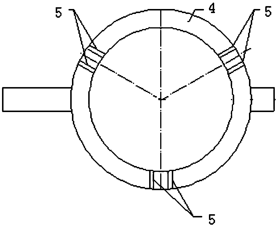
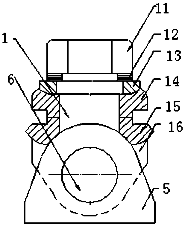
[0072] combine Figure 1-5 , a three-point spherical support installation auxiliary device, including a three-point support seat 5, a false shaft pin 6 and a temporary rigid support II112, spaced 120° along the circumferential direction of the support ring 4, forming three points evenly distributed, the center of these three points A three-point support seat 5 is arranged symmetrically on both sides of the line, and the dummy shaft pin 6 is located between the inner sides of the two mutually symmetrical three-point support seats 5, and on the outside of the two mutually symmetrical three-point support seats 5, with respect to the center line A temporary rigid support II112 is arranged symmetrically, one end of the temporary rigid support II112 is welded on the support ring 4, and the other end is welded on the top of the outer surface of the three-point support seat 5. Both sides of the three-point support seat 5 are supported by the temporary rigid support II112, and a false ...

Embodiment 2

[0112] This embodiment is the same as Embodiment 1, wherein the auxiliary device is installed with three-point spherical support, the shaft hole is finished first, and the deformation is precisely controlled by welding, so that the original secondary processing and secondary assembly procedures are reduced to one-time completion. The manufacturing cost is effectively reduced and the manufacturing period is shortened.

[0113] The three-point spherical support device is connected to the three-point support seat 5 on the upper part of the support ring 4 with three support pins at 120° each other, which can swing freely on the pin shaft, and its upper part is connected to the furnace shell through two pairs of spherical washers The pin holes of the flange are locked with nuts. Under the lock nuts (nut 11), there is a group of four corrugated washers with small height and large load-bearing capacity. The supporting bolts can swing freely against the two pairs of spherical surfaces....


PUM


Abstract

The invention discloses a mounting assisting device for a three-point spherical bearing and a mounting-welding method of the mounting assisting device. The mounting assisting device comprises three-point support seats, a dummy shaft pin and temporary rigid supports II, wherein three points are uniformly formed at intervals of 120 degrees along the peripheral direction of a support ring, two three-point support seats are respectively symmetrically arranged on two sides of the center line of the three points, and the dummy shaft pin is located between the inner sides of the two mutually symmetric three-point support seats; and the temporary rigid supports II are symmetrically arranged relative to the center line outside the two mutually symmetric three-point support seats. Two sides of the three-point support seats are supported by the temporary rigid supports II, the dummy shaft pin is arranged between the three-point support seats to maintain the required mounting size, the temporary rigid supports II and the dummy shaft pin act together to enable the axial direction of the three-point support seats to be parallel to the plane on which the support ring is located, so that the side surfaces of the three-point support seats are vertical to the plane on which the support ring is located, the distances from the upper parts to the lower parts of the inner sides of the two three-point support seats are equal, and the mounting and the welding are prepared.

Description

technical field [0001] The invention relates to the field of metallurgical machinery and equipment, in particular to a three-point spherical support installation auxiliary device and an installation welding method thereof. Background technique [0002] The connection device between the converter shell and the support ring is one of the key equipment in the converter system. In the converter steelmaking operation, it not only has to bear the weight of the converter full of molten steel, but also ensures that the converter can tilt smoothly. In the process, The connecting device is subject to very large moments of tension, compression, twisting, etc., and is prone to tearing. Therefore, the welding quality and accuracy of the connecting device are very important. At present, there are mainly two kinds of connection devices between the converter shell and the support ring in my country, one is a three-point support connection method, and the other is a suspension connection met...

Claims


Application Information

Patent Timeline
Patent Type & Authority Applications(China)
IPC IPC(8): B23K37/04B23K9/12B23K9/235
CPCB23K9/12B23K9/235B23K37/0417
Inventor 张烨
Owner ANHUI MASTEEL ENG & TECH GRP
Learn More