
Construction method of gradient silica surface microfluidic system

A microfluidic system, silica technology, applied in chemical instruments and methods, laboratory containers, laboratory utensils, etc., can solve the problem of not being able to convert interface free energy into droplet mechanical energy, etc., to enhance the capillary driving force Effect

Active Publication Date: 2017-07-04
UNIV OF SCI & TECH BEIJING
View PDF5 Cites 0 Cited by
  • Summary
  • Abstract
  • Description
  • Claims
  • Application Information

AI Technical Summary

Problems solved by technology

However, most surfaces of these methods cannot directly and spontaneously convert the interfacial free energy into droplet mechanical energy, but require other external forces to catalyze

Method used


Image

  • Construction method of gradient silica surface microfluidic system
  • Construction method of gradient silica surface microfluidic system
  • Construction method of gradient silica surface microfluidic system

Examples


preparation example Construction

[0041] SiO 2 The preparation of the nano film layer is obtained by the hydrolysis of ethyl orthosilicate and ammonia water or silicon tetrachloride, and is carried out by chemical vapor deposition. Specifically, place two containers (two kinds of reagents with the same volume) and the sample obtained in step 1 in an airtight desiccator that are respectively multiplied by tetraethyl orthosilicate and ammonia water, or replace the reagent with silicon tetrachloride. The relative humidity is 60% RH, and the ambient temperature is 30°C, put it in a blast drying oven for 12-24 hours, take it out, heat-treat at 400-600°C for 1-3 hours, remove the soot layer and other organic matter, and cool it naturally for later use.

[0042] 3), Modified SiO with hydrophobic material 2 Nano film layer, forming a hydrophobic layer;

[0043] Hydrophobic material is selected from alkyltrichlorosilane (Cl 3 Si(CH 2 ) n CH 3 , n=8~16) chemical reagents. Soak the sample in 3-10mmol alkyltrichlor...

Embodiment 1

[0047] Step 1, get common glass slide, slide glass is soaked in piranha solution (98%H 2 SO 4and 30%H 2 o 2 , mixed in a ratio of 3:1), placed on a heating plate at 200°C and heated for 1 hour, after taking it out, use acetone, ethanol, and deionized water to perform ultrasonic purification at room temperature for 10 minutes each, and then blow dry with nitrogen .

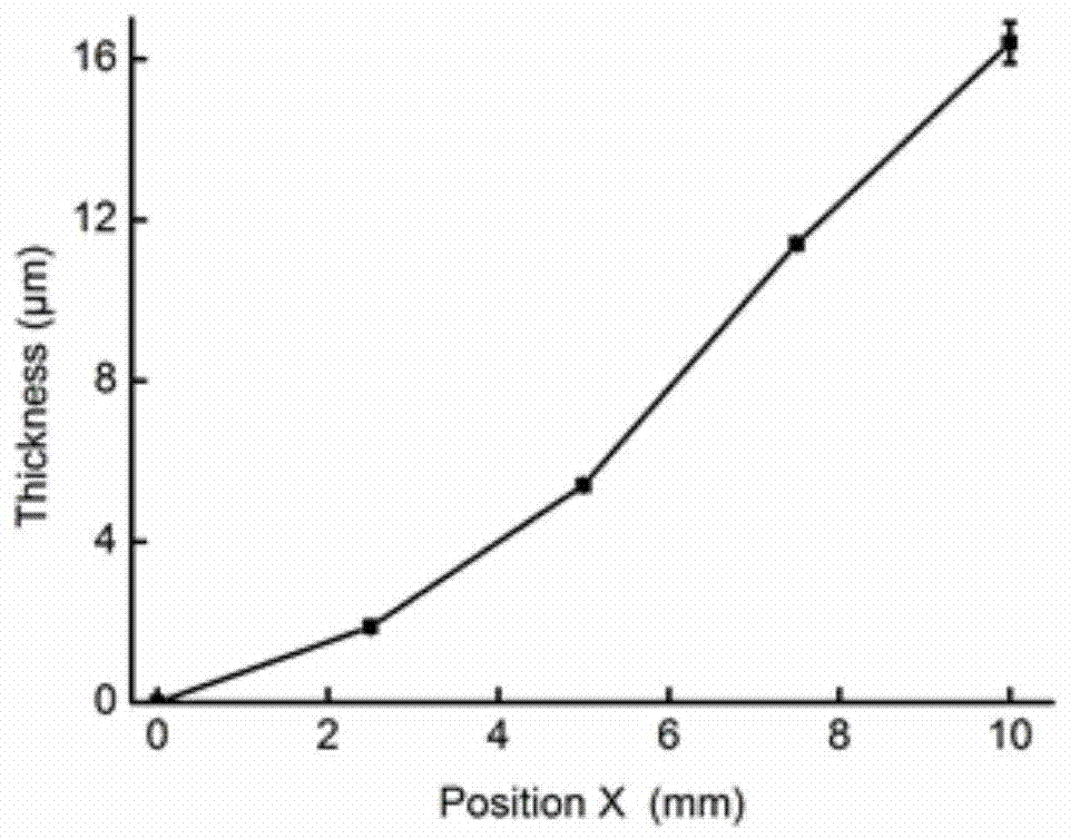
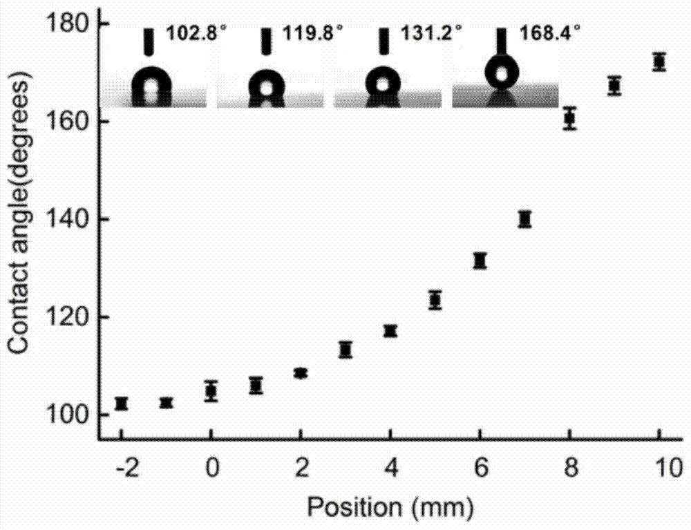
[0048] Step 2. Place the cleaned glass slide at an angle of 45° at 0.5 cm above the candle flame for 5 seconds to obtain a porous network-like soot structure with a gradient.

[0049] Step 3. Place the obtained sample together with two containers multiplied by 4mL tetraethyl orthosilicate and 4mL ammonia water in a closed desiccator in a blast drying oven with a relative humidity of 60% RH and an ambient temperature of 30°C Placed in the middle for 24 hours, the hydrolysis of tetraethyl orthosilicate and ammonia water will generate SiO 2 Coated on the outside of soot particles to form SiO with a thickness of 2...

Embodiment 2

[0055] Embodiment 2 and embodiment 1 only generate SiO in step 3 2 The method of shelling is different. In Example 2, the obtained soot layer substrate was airtightly placed in a petri dish together with 100 μL of silicon tetrachloride solution, and placed in a blast drying oven with a relative humidity of 60% RH and an ambient temperature of 30° C. for 12 hours.

[0056] Other preparation method is the same as embodiment 1, also can be in SiO 2 A superhydrophilic-hydrophobic microfluidic channel is formed on the surface of the membrane layer.


PUM


Abstract

Embodiments of the present invention provide a gradient silica surface microfluidic system construction method based on ultra-hydrophilic-hydrophobic property. The method comprises: forming a flue dust layer having gradient on the carrier surface; forming a SiO2 nanometer film layer on the flue dust layer surface having the gradient; modifying the SiO2 nanometer film layer by using a hydrophobic material to form a hydrophobized SiO2 nanometer layer; and covering a photomask on the hydrophobized SiO2 nanometer layer, and carrying out ultraviolet light irradiation so as to form the ultra-hydrophilic-hydrophobic microfluid on the SiO2 nanometer structure film layer surface. According to the technical scheme of the present invention, the porous mesh flue dust structure having the surface gradient is used to obtain the porous mesh SiO2 structure having the surface gradient, the ultra-hydrophilic-hydrophobic property is used to prepare the microfluid channel, and the gradient and the microfluid channel are cleverly combined to enhance the capillary driving force of the microfluid so as to rapidly complete self-delivery of the fluid in the absence of external force.

Description

technical field [0001] The invention relates to the technical field of material preparation and detection and analysis, in particular to a method for constructing a gradient silicon dioxide surface microfluidic system based on superhydrophilic-hydrophobic properties. Background technique [0002] As an interdisciplinary research field, microfluidic systems have become a hot research topic at home and abroad, and are widely used in the fields of biomedicine and chemistry, such as gene analysis, drug development, food safety, environmental monitoring, chemical reactions, etc. [0003] Microfluidic drive technology is one of the key technologies in microfluidic systems, and it is the premise and basis for realizing precise fluid control in microfluidic systems. Microfluidic drive technology mainly converts energy in the form of electrical energy, magnetic energy, thermal energy, chemical energy, and mechanical energy into kinetic energy and potential energy of microfluidics. A...

Claims


Application Information

Patent Timeline
Patent Type & Authority Patents(China)
IPC IPC(8): B01L3/00
Inventor 许利苹曹艳华廖新勤杨高王书琪魏璐王树涛张学记
Owner UNIV OF SCI & TECH BEIJING
Learn More