Reaction kettle and three-phase flow catalytic reaction method applying same

A reaction kettle and reaction technology, applied in chemical instruments and methods, chemical/physical/physical chemical nozzle reactors, chemical/physical processes, etc. Process steps and other issues to achieve the effect of increasing the contact area of ​​raw materials, simplifying equipment and processes, and accelerating the mixing speed

Active Publication Date: 2016-04-20
CHENGDU INTERMENT TECH
View PDF5 Cites 0 Cited by
  • Summary
  • Abstract
  • Description
  • Claims
  • Application Information

AI Technical Summary

Problems solved by technology

Such production equipment has a complex structure, which also increases the process steps in production, and also increases the loss probability of products and catalysts
The reason why such problems exist in the prior art is that those skilled in the art have not designed a suitable filter structure that can be installed in the reactor and will not cause damage to the original equipment in the reactor. Secondly, the working environment in the reaction kettle is generally corrosive and harsh in chemical reactions. It is difficult to find a filter material that can perform filtering, back blowing and mechanical stirring and vibration in such harsh working conditions. Long-term stable operation
[0011] In summary, it can be seen that currently, for the three-phase flow catalytic reaction, there is a lack of an ideal high-efficiency production equipment and reaction production method.

Method used


Image

  • Reaction kettle and three-phase flow catalytic reaction method applying same
  • Reaction kettle and three-phase flow catalytic reaction method applying same
  • Reaction kettle and three-phase flow catalytic reaction method applying same

Examples


Embodiment 1

[0054] Example as Figure 1 to Figure 3 shown.

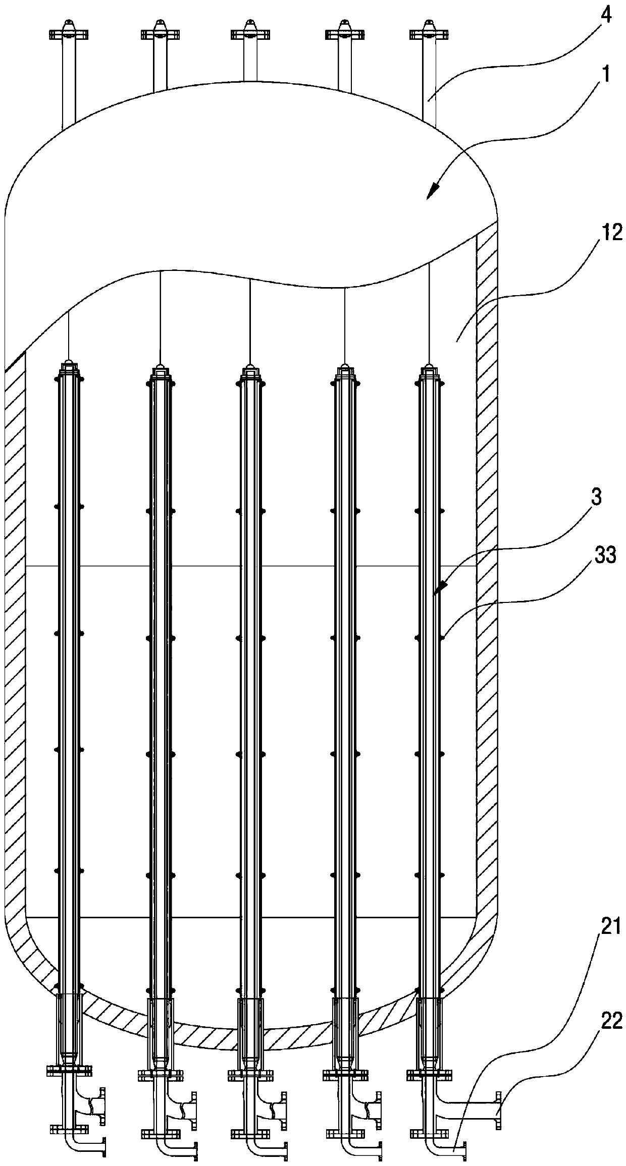
[0055] Such as figure 1 As shown, the reaction kettle in Embodiment 1 includes a kettle body 1 , which is surrounded by a shell to form a structure with a cavity inside, and the cavity in the kettle body 1 is a reaction chamber 12 .

[0056] Wherein the position of the lower bottom end of the kettle body 1 is connected with a plurality of feeding ports 21 and discharging ports 22 which are independent of each other. In addition, each feed port 21 and each discharge port 22 are set independently of each other. Of course, the upstream of each feed port 21 is connected to a main channel for raw material transportation. Correspondingly, each of the discharge ports The downstream of port 22 is commonly connected with a trunk passage for conveying finished products.

[0057] At the same time, in the first embodiment, a plurality of vertical tubular structure guide structures 3 are placed in the reaction chamber 12 in the kettle bod...

Embodiment 2

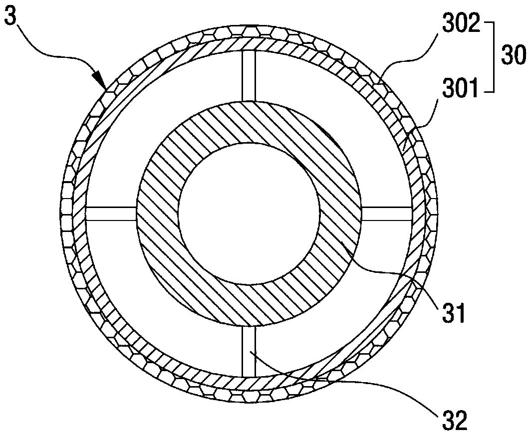
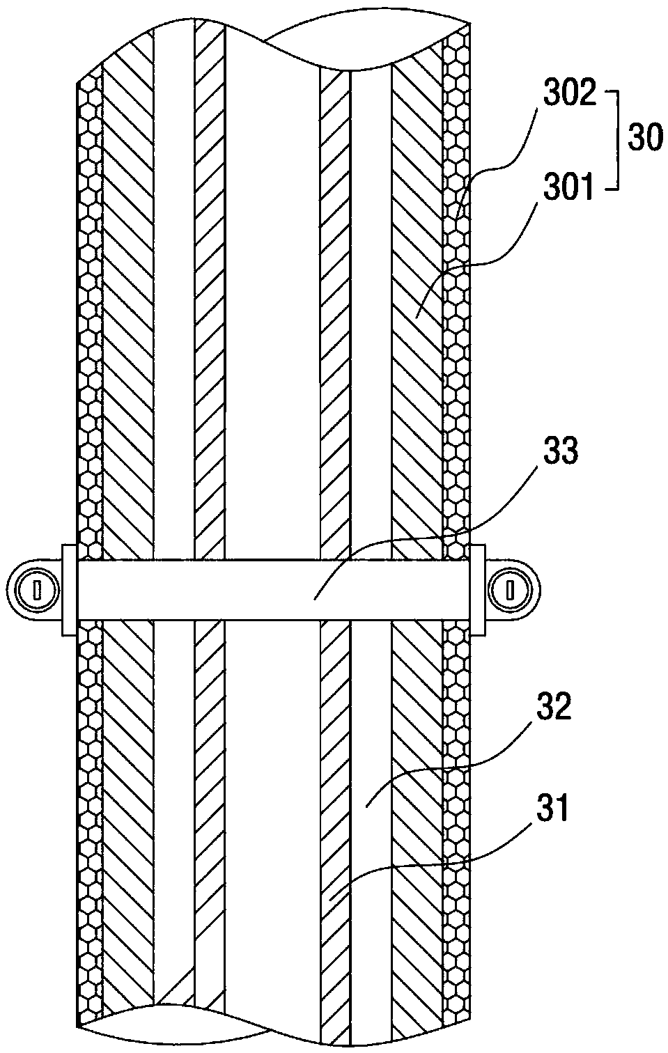
[0076] Example two such as Figure 4 As shown, the reaction kettle in this embodiment includes a kettle body 1, and the kettle body 1 is provided with a reaction chamber 12, and the reaction chamber 12 includes a plurality of pipe-shaped flow guide structures 3, and the flow guide structure 3 includes the permeable component 30 composed of the flexible porous metal foil used above as the filter material 302 pasted on the first support body 301.

[0077] Some of the diversion structures 3 are divided into two types, one is that the first diversion structure 3a is located in the reaction chamber 12 and communicates with the feed port 21; the other is that the second diversion structure 3b is located in the reaction chamber 12 And communicate with the discharge port 22. After passing the reactants from the first flow guide structure 3 a into the reaction chamber 12 for reaction, they are discharged from the second flow guide structure 3 b through the outlet 22 .


PUM


Abstract

The invention relates to a reaction kettle and a three-phase flow catalytic reaction method applying the same. The invention aims to provide the reaction kettle high in production efficiency and meanwhile provide the three-phase flow catalytic reaction method applying the reaction kettle. The invention relates to the field of chemical industrial reaction equipment. In order to achieve the purpose, the reaction kettle comprises a kettle body, wherein a reaction chamber is formed in the kettle body; a flow guiding structure is arranged in the reaction chamber and comprises a permeating part; a feeding hole and a discharging hole are communicated with the flow guiding structure or the flow guiding structure comprises a first flow guiding structure and a second flow guiding structure; the feeding hole is communicated with the first flow guiding structure; the discharging hole is communicated with the second flow guiding structure; reactants are introduced through the feeding hole and then react after entering into the reaction chamber through the permeating part; acquired products are discharged from the discharging hole communicated with the flow guiding structure through the permeating part. Meanwhile, the invention also provides the three-phase flow catalytic reaction method applying the reaction kettle.

Description

technical field [0001] The field that the present invention relates to is a kind of field of chemical reaction equipment, especially relates to the field of three-phase flow reaction. Background technique [0002] In the prior art, in the field of chemical industry, two methods are commonly used for the reaction of liquid-phase and gas-phase substances in the dispersion system, and the production reaction catalyzed by solid-phase catalysts: [0003] The first is to use a fixed bed as a catalyst carrier to fix the catalyst in the reactor, and use the liquid phase and the gas phase in the dispersion system to mix and then contact the catalytic bed to realize the catalytic reaction. [0004] In this kind of reactor, the position of the catalyst in the reactor is relatively fixed, and the position of the catalyst in the reactor generally does not disperse and move, so there is no need to consider filtering and separating the catalyst and the product after the reaction is complet...

Claims


Application Information

Patent Timeline
Patent Type & Authority Applications(China)
IPC IPC(8): B01J8/08B01J19/26
CPCB01J8/006B01J8/085B01J19/0053B01J19/26B01J2208/00902
Inventor 高麟汪涛樊彬
Owner CHENGDU INTERMENT TECH
Why Eureka
Try Eureka