
an emulsifying machine

A technology of emulsifying machine and emulsifying tank, applied in the field of emulsifying machine, can solve the problems of small impact force of emulsifying tank, single material movement trajectory, poor stirring effect, etc., and achieve the effect of enhancing emulsifying ability and improving emulsifying effect.

Inactive Publication Date: 2018-08-03
北京空港东辉科技发展有限公司
View PDF7 Cites 0 Cited by
  • Summary
  • Abstract
  • Description
  • Claims
  • Application Information

AI Technical Summary

Problems solved by technology

However, the emulsification axis of this invention is arranged longitudinally in the emulsification tank. During the emulsification process, the movement of the medium is mainly concentric rotation along the side wall of the emulsification tank. The material movement track is single, and the medium moves along the inner side wall of the emulsification tank. The impact force of the medium on the emulsification tank is small, and the emulsification effect of the emulsification tank on the medium is not exerted, resulting in poor stirring effect. In addition, there is a low stirring intensity of the material at the intersection of the bottom of the emulsification tank and the side wall, which makes the emulsification tank difficult to clean. Blind spots appear

Method used


Image

  • an emulsifying machine

Examples


Embodiment Construction

[0012] The present invention will be further described in detail below in conjunction with the accompanying drawings and embodiments.

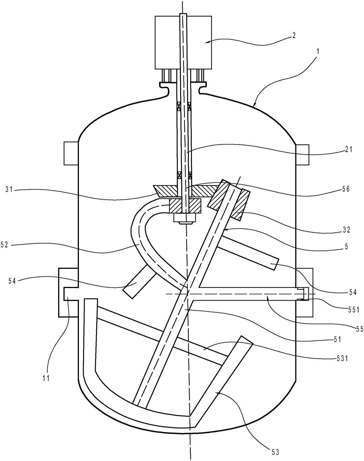
[0013] Such as figure 1 As shown, the emulsification machine in this implementation includes an emulsification tank 1 , a driving motor 2 and an emulsification assembly 5 .

[0014] Wherein, the drive motor 2 is arranged outside the emulsification tank 1 , and the emulsification assembly 5 is placed inside the emulsification tank 1 . The driving motor 2 is a hollow motor, and the driving motor 2 includes a drive shaft 21 arranged longitudinally. Be located in the driving shaft 21, the bearing shaft 56 and the driving shaft 21 clearance fit, the lower end of the bearing shaft 56 passes outside the driving shaft 21, the driving shaft 21 end is provided with the first bevel gear 31, and the emulsifying shaft 56 is provided with the first bevel gear at one end. The second bevel gear 32 driven by the first bevel gear 31, the other end of the emul...


PUM


Abstract

The invention discloses an emulsification machine, which comprises an emulsification tank, a drive motor arranged outside the emulsification tank and an emulsification assembly placed in the emulsification tank, and is characterized in that: the drive motor is a hollow motor, and the drive motor includes a drive motor arranged longitudinally shaft, the driving shaft is hollow, and the emulsification assembly includes a fixed bearing shaft, an emulsification shaft and a curved connecting shaft, the bearing shaft is installed in the driving shaft, the bearing shaft and the driving shaft are in clearance fit, and the lower end of the bearing shaft passes out of the driving shaft , the end of the drive shaft is provided with a first bevel gear, one end of the emulsification shaft is provided with a second bevel gear that is driven by the first bevel gear, the other end of the emulsification shaft is provided with a stirring blade, and the axis of the bearing shaft intersects the axis of the emulsification shaft One point, the outer shape of the stirring blade is adapted to the shape of the inner wall at the junction of the bottom wall and the side wall of the emulsification tank, one end of the connecting shaft is rotatably connected to the end of the bearing shaft, and the other end of the connecting shaft is fixedly connected to the emulsification shaft.

Description

technical field [0001] The invention relates to an emulsifying device, in particular to an emulsifying machine. Background technique [0002] At present, the devices for emulsifying media in the fields of refinement and construction chemical industry at home and abroad mainly include emulsification tanks, emulsification components and drive motors. The drive motor is used to drive the emulsification component to stir the medium in the emulsification tank, so that the emulsification of the medium is realized by shearing, dispersing and impacting the medium. [0003] For example, the Chinese invention with the existing patent number ZL201410113725.1 discloses "High-efficiency high-shear emulsification machine", which includes: electric motor, double output shaft gearbox, central stirring paddle, external stirring paddle, emulsification tank, and the emulsification tank is cylindrical Shaped structure, the top of the emulsification tank is equipped with a cover plate, and the ...

Claims


Application Information

Patent Timeline
Patent Type & Authority Patents(China)
IPC IPC(8): B01F7/20B01F3/08B01F27/906
CPCB01F23/41B01F27/0723B01F27/0725B01F27/071B01F27/1122B01F27/2121B01F27/2122B01F27/906
Inventor 吴洋
Owner 北京空港东辉科技发展有限公司
Learn More