Textile machines with stand-alone dust collectors

A technology for dust collectors and textile machines, which is applied in the direction of dust removal, chemical instruments and methods, and separation of dispersed particles. It can solve the problems of dust flying, low dust collection efficiency, and low dust removal efficiency, so as to achieve convenient disassembly and installation, and reduce dust removal. The effect of high load and dust removal efficiency

Inactive Publication Date: 2017-08-25
HUZHOU NANXUN SHICONG SHENGYAN SILK
View PDF8 Cites 0 Cited by
  • Summary
  • Abstract
  • Description
  • Claims
  • Application Information

AI Technical Summary

Problems solved by technology

During the working process of the textile machine, a large amount of dust will appear during the processing of raw materials such as thread, silk, and hemp. The negative charge of the negative charge is easily adsorbed on the machine tool or the body of the worker, and even enters the nasal cavity of the human body, causing physical discomfort and serious damage to human health.
The existing dust removal device used on the textile machine simply connects the suction fan with the dust delivery pipe, the dust collection efficiency is very low, and it cannot play any dust removal effect on some dust adsorbed on the machine tool, so it takes a long time , the dust on the machine tool will accumulate thicker and thicker, which is not conducive to the cleaning of the machine tool, but also affects the quality of the product
Therefore, the current dust removal device for textile machines has the problems of low dust removal efficiency and incomplete dust removal.

Method used


Image

  • Textile machines with stand-alone dust collectors

Examples


Embodiment Construction

[0014] The present invention will be further described below in conjunction with the accompanying drawings and embodiments, but not as a basis for limiting the present invention.

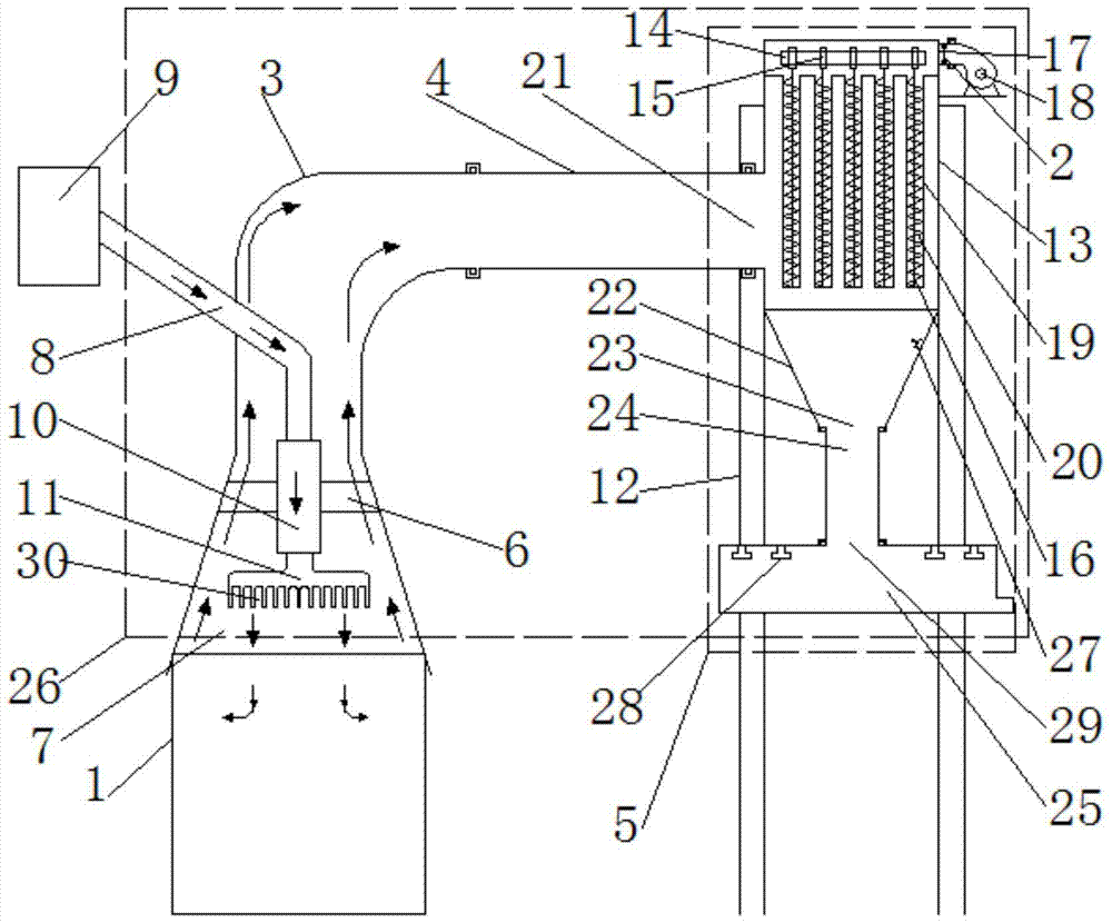
[0015] Example. Textile machines with stand-alone dust collectors, constituted as figure 1 As shown, the textile machine 1 is included, and a dust removal mechanism 26 is also included; the dust removal mechanism 26 includes a first dust suction pipe 3, the inlet end of the first dust suction pipe 3 is located above the textile machine 1, and the outlet of the first dust suction pipe 3 The second dust suction pipe 4 is connected to the end, and the dust collector 5 is connected to the second dust suction pipe 4; the lower part of the first dust suction pipe 3 is in the shape of a bell mouth, and the upper part of the first dust suction pipe 3 is "L". Shape, the bell mouth place in the first suction pipe 3 is provided with shock absorber 6, and air cannon 7 is fixed on the shock absorber 6, and air ...


PUM


Abstract

The invention discloses a textile machine with a single machine dust remover, which comprises a textile machine and a dust removal mechanism; the dust removal mechanism includes a first dust suction pipe, a second dust suction pipe and a dust collector; The shock mount has an air cannon fixed on the shock mount; the air cannon includes a buffer cavity, an air equalization cavity, an equal air cavity and a plurality of needle-shaped air nozzles; There are multiple electromagnets on the rod, and there are drawstrings on the electromagnets; the side above the box is equipped with a suction device; inside the box, there are multiple net bags hanging in rows, and springs are arranged in the net bags; The lower side of the box is connected to the second suction pipe; the lower end of the box is provided with an ash hopper, the inner wall of the ash hopper is provided with an atomizing nozzle, the lower end of the ash hopper is connected with a dust guide tube, and the upper part of the dust guide tube is connected There is a dust outlet pipe, and a plurality of water spray heads are arranged side by side in the dust outlet pipe. The invention has the characteristics of high dust removal efficiency and thorough dust removal.

Description

technical field [0001] The invention relates to the technical field of textile machinery, in particular to a textile machine with a single-machine dust collector. Background technique [0002] Textile machine is exactly the full name of the tool that the raw material such as thread, silk, fiber crops is processed into silk thread and then is woven into cloth. During the working process of the textile machine, a large amount of dust will appear during the processing of raw materials such as thread, silk, and hemp. The negative charge of the negative charge is easily adsorbed on the machine tool or the body of the worker, and even enters the nasal cavity of the human body, causing physical discomfort and seriously damaging human health. The existing dust removal device used on the textile machine simply connects the suction fan with the dust delivery pipe, the dust collection efficiency is very low, and it cannot play any dust removal effect on some dust adsorbed on the machi...

Claims


Application Information

Patent Timeline
Patent Type & Authority Patents(China)
IPC IPC(8): B01D50/00B08B15/04
CPCB08B15/04B01D50/60
Inventor 严金娜沈新荣
Owner HUZHOU NANXUN SHICONG SHENGYAN SILK
Why Eureka
Try Eureka